Unpacking, Assembly – Winco 75FPTOC-17 User Manual
Page 4
Page 2
60706-125
7315-000
Description
The WINCO PTO drive generator will provide, depending on
the unit purchased, 120/240V single phase, 120/240V three
phase or 120/208 three phase 60Hz electrical service when
direct-driven. Tractor or vehicle power take-off shafts, can be
used for driving these generators.
NOTE: The prime mover which drives the generator must be
capable of delivering approximately 2 HP per 1000 watts
output from the generator. Observe input RPM specifications.
The generator may be foundation mounted for use as standby
power source, or trailer mounted, and used as portable
electrical power sources for areas where commercial power
is not readily available, such as out buildings.
This generator includes a load sensing transformer which
provides extra motor starting power, a color coded voltmeter to
warn against high or low voltage, three output power recep-
tacles, an overload protection circuit, and an electronic
excitation circuit. To reduce maintenance problems, the
coupling between the generator input shaft and rotor consists
of precision helical gearing rather than a chain link drive. The
input shaft is splined, and is 1-3/8 in diameter.
The factory thoroughly tests each of these generators before
shipment. All are continuous duty rated.
IMPORTANT: THE MANUFACTURER STRONGLY RECOM-
MENDS RUNNING THE GENERATOR UNDER LOAD AT
LEAST ONCE A MONTH IN ORDER TO EVAPORATE ANY
ACCUMULATED MOISTURE CONDENSATION
UNPACKING
CAUTION: Equipment Damage
DO NOT invert generator during unpacking. The Gearcase
contains oil which will leak out if inverted during unpacking.
Unpack the generator as follows:
1. Remove the carton.
2. Examine the unit for damage.
3. Find the small subpack carton packed in the large carton.
Be careful not to throw away the subpack carton with the large
carton.
4. Open the subpack carton and make sure it contains:
a. Generator instruction manual
b. Load disconnect plug (disassembled, in bag)
5. Remove the four bolts which hold down the generator feet
to the pallet.
6. Lift the generator from the pallet by means of the lifting eye
on the top of the generator.
7. Inspect the generator carefully for freight loss or damage. If
loss or damage is noted at time of delivery, require that the
person making the delivery make note of the loss or damage
on the freight bill, or sign the consigner’s memo of the loss or
damage. Contact the carrier for claim procedures.
When loss or damage is noted after delivery, segregate the
damaged material, and contact the carrier for claim proce-
dures.
“Concealed damage” means damage to the contents of a
package which is not evident when the package is delivered
by the carrier, but which is discovered later. The carrier or
carriers are responsible for merchandise lost or damaged in
transit. The title to the goods rests with the consignee when
the goods are shipped FOB factory, and only the consignee
can legally file claims. Two years are allowed in which to file
suit after a claim is disallowed in writing by the carrier.
Assembly
The only assembly work required after unpacking the genera-
tor is to assemble and wire the load disconnect plug, which is
contained in a bag in the subpack carton packed in the
generator crate. The bag contains an instruction sheet, a plug
body, three or four brass pins (large pin for neutral line), and a
small envelope. The small envelope contains an allen
wrench, retainer pins, and set screws.
To wire the load disconnect plug, use the following type of
cable:
Generator
Size,
Model
AWG
Insulation
35PTOC-3
1
600V, THW
40PTOC-4
4
600V, Neoprene
45PTOC-17
4
600V, Neoprene
50PTOC-3
1
600V, THW
55PTOC-3
1
600V, THW
75PTOC-4
1
600V, THW
75PTOC-17
1
600V, THW
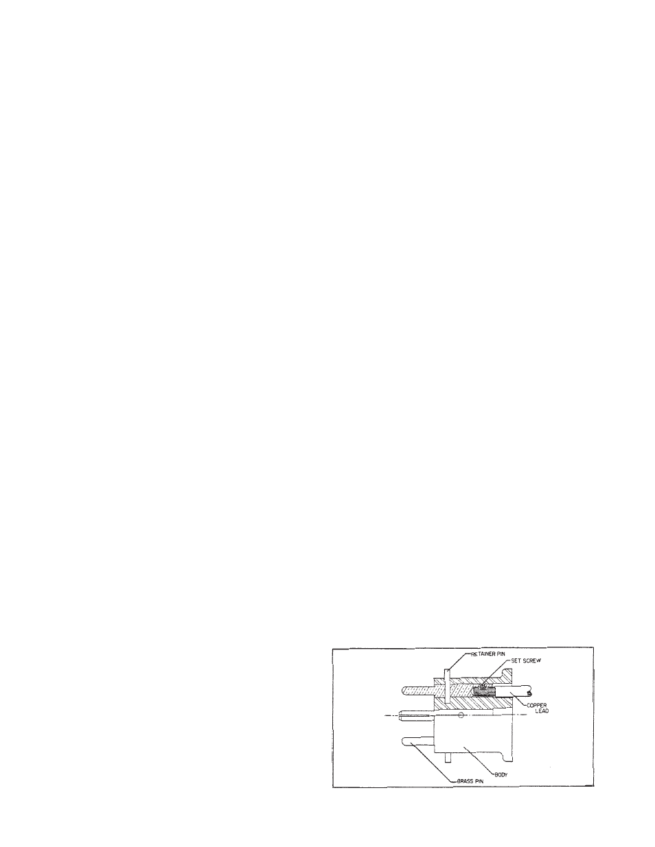
To assemble and wire the load disconnect plug,
proceed as follows (see Figure 1):
1. Cut cables to the required length.
2. Strip off insulation 7/8" back from one end of each cut-to-
length cables.
3. Start threading a set screw into each pin.
4. Insert the stripped end of one cable fully into one of the
brass pins, and tighten the set screw firmly to secure the
cable end in the pin.
Octopus Plug Assembly
Figure 1