Winco PSS65LS-*/B User Manual
Page 9
60706-144
Page 7
1017-10
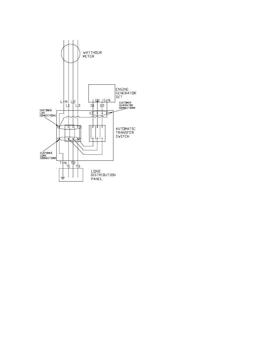
Three phase unit shown, for single phase wir-
ing disregard L-2, T-2, G-2.
The automatic transfer switch connects the load (lights,
furnace, outlets, etc.) to the normal power line. When nor-
mal power fails, the A.T.S. starts the engine generator set,
disconnects the power line and then connects the load to
the standby generator set. When normal power is re-
stored, the automatic switch retransfers the electrical load
to the normal service and stops the engine. The A.T.S.
panel should be mounted as close to the distribution panel
as possible.
*************
***** WARNING *****
*************
FIRE HAZARD - All wiring must be done by a licensed
electrician, and must conform to the national electrical
code and comply with all state and local codes and regula-
tions. Check with the authorities before proceeding!
PSS50000 - The Automatic Transfer Switch shipped with
the PSS50000 single phase units have 400 Amp line side
contactors installed to handle your normal power needs
and a 320 Amp generator side contactor to handle the
emergency generator output. For the three phase 240 volt
and 208 volt units the Automatic Transfer Switches come
with 230 Amp line side and generator side contactors. If
you are installing a 480 volt system check the Transfer
Switch for its contact rating. Before installing the A.T.S.
you must first ensure that the line side contactor will be
FIGURE 5
sufficient to handle your complete service. (I.E. your main
line breaker rating does not exceed the line side contactor
rating.) See Figure 5. If you have a larger main line
breaker, you will not be able to transfer the complete elec-
trical system. In this case it will be necessary to install a
secondary emergency distribution panel
PSS65000 - The Automatic Transfer Switch shipped
with the PSS65000 single phase units have 400 Amp line
side contactors installed to handle your normal power
needs and a 320 Amp generator side contactor to handle
the emergency generator output. For the three phase 240
volt and 208 volt units the Automatic Transfer Switches
come with 230 Amp line side and generator side contac-
tors. If you are installing a 480 volt system check the
Transfer Switch for its contact rating. Before installing the
A.T.S. you must first ensure that the line side contactor will
be sufficient to handle your complete service. (I.E. your
main line breaker rating does not exceed the line side con-
tactor rating.) See Figure 5. If you have a larger main line
breaker, you will not be able to transfer the complete elec-
trical system. In this case it will be necessary to install a
secondary emergency distribution panel
*****NOTE*****
EQUIPMENT DAMAGE- The standard single phase
Winco ATS does not protect against undervoltage. If you
are in an area that is susceptible to brown outs (low volt-
age) you may want to consider adding an undervoltage
sensor to standard ATS panel.
*************
***** WARNING *****
*************
PERSONAL INJURY - Be certain the operation selector
switch on the front of the A.T.S. Control is in the “stop” po-
sition and the main power switch “off”. For your own pro-
tection, verify these important safety precautions yourself
with reliable instruments before proceeding.
A.C. ELECTRICAL CONNECTIONS
Single Phase
*************
***** WARNING *****
*************
A FUSED DISCONNECT OR CIRCUIT BREAKER
MUST BE INSTALLED BETWEEN THE GENERATOR
AND THE A.T.S. PANEL TO PREVENT OVERLOADING
AND BURNING OUT THE GENERATOR. FAILURE TO
PROVIDE A FUSED DISCONNECT OR CIRCUIT
BREAKER, RATED AT GENERATOR RATING WILL VOID
YOUR WARRANTY IN CASE OF GENERATOR FAILURE.
The standby generator terminals in the A.T.S are marked
“GENERATOR - G1, G-N, G3”. The “hot” leads G1 and G3
wire directly to the lugs on the generator side contactor,
terminals G1 and G3. The G-N connection is made at the
neutral bar on the standoffs on the floor of the A.T.S.