Winco PSS65LS-*/B User Manual
Page 7
60706-144
Page 5
1017-10
Fuel Pressure Table
Single Regulator (L.P. Vapor only)
1
2
3
UNIT OFF
TANK PSI
7-11 in 7-11 in
4-6 oz 4-6 oz
STARTING
TANK PSI
7-11 in 7-11 in
4-6 oz 4-6 oz
NO LOAD
TANK PSI
7-11 in 7-11 in
4-6 oz 4-6 oz
FULL LOAD
TANK PSI
7-11 in 7-11 in
4-6 oz 4-6 oz
Two (2) Regulator System (L.P. Vapor only)
1
2
3
4
UNIT OFF
TANK PSI 10-15 lbs
7-11 in
7-11 in
4-6 oz
4-6oz
STARTING TANK PSI 10-15 lbs
7-11 in
7-11 in
4-6 oz
4-6 oz
NO LOAD
TANK PSI 10-15 lbs
7-11 in
7-11 in
4-6 oz
4-6 oz
FULL LOAD TANK PSI 10-15 lbs
7-11 in
7-11 in
4-6 oz
4-6 oz
Natural Gas
1
3
4
UNIT OFF
LINE PSI
7-11 in
7-11 in
4-6 oz
4-6 oz
STARTING
LINE PSI
7-11 in
7-11 in
4-6 oz
4-6 oz
NO LOAD
LINE PSI
7-11 in
7-11 in
4-6 oz
4-6 oz
FULL LOAD
LINE PSI
7-11 in.
7-11 in
4-6 oz
4-6 oz
Notice the preceding tables give two (2) different units
of measuring fuel pressure. The first is with a pressure
gauge calibrated in ounces per square inch. The second
and most accurate is the use of a simple water manome-
ter. A manometer is calibrated in inches of water column.
LP LIQUID WITHDRAWAL SYSTEMS
When installing a unit equipped the LP liquid withdrawal
a primary regulator is not required on the supply tank.
The supply line is connected to a liquid withdrawal valve
on the supply tank and run directly to the fuellock strainer
mounted on the engine generator set. Normally a 3/8 inch
copper line is acceptable for this type of fuel installation.
You must be sure that the valve you have connected to on
the supply tank is in fact a liquid supply valve and has a
drop tube inside the tank that is pulling fuel from the bot-
tom of the supply tank. Before starting the unit you must
confirm that you have a good liquid supply at the unit. En-
gine generator sets equipped for liquid withdrawal will
not run properly when supplied with high pressure va-
por fuel.
The following is a block diagram of a typical L/P Liquid
Withdrawal fuel system.
generally adequate for distances up to 300 feet from the
primary to the secondary regulator. (Consult your local
fuel supplier for your exact requirements). The appropriate
line size from the table below is then installed from the
second regulator to the generator set.
*************
***** WARNING ****
*************
PERSONAL DANGER - Do not use galvanized pipe in
fuel line runs. The galvanized coating can become eroded
and flake off, causing possible obstructions in the regulator
or fuel valve. The results could range from inoperative en-
gine start to hazardous fuel leaks.
Size of pipe normally required for generators operating
on NATURAL/LP gas.
up to 25 feet* over 25 feet*
PSS50000 1-1/4" pipe
Not recommended use
PSS65000 1-1/4" pipe a two regulator
system
* Allow an additional 3 feet for each standard elbow.
Do not use ‘street ells’ (restrictive)*
**** CAUTION ****
EQUIPMENT DAMAGE - Be careful when sealing gas
joints. Excessive sealing compound can be drawn into the
solenoid, regulator or carburetor causing an engine mal-
function.
FUEL PRESSURE (vapor system)
Correct fuel pressure cannot be stressed enough. The
most common cause for inoperative systems is an inade-
quate or incorrect fuel pressure. Performance of the en-
gine is in direct relation to the correctness of the fuel sys-
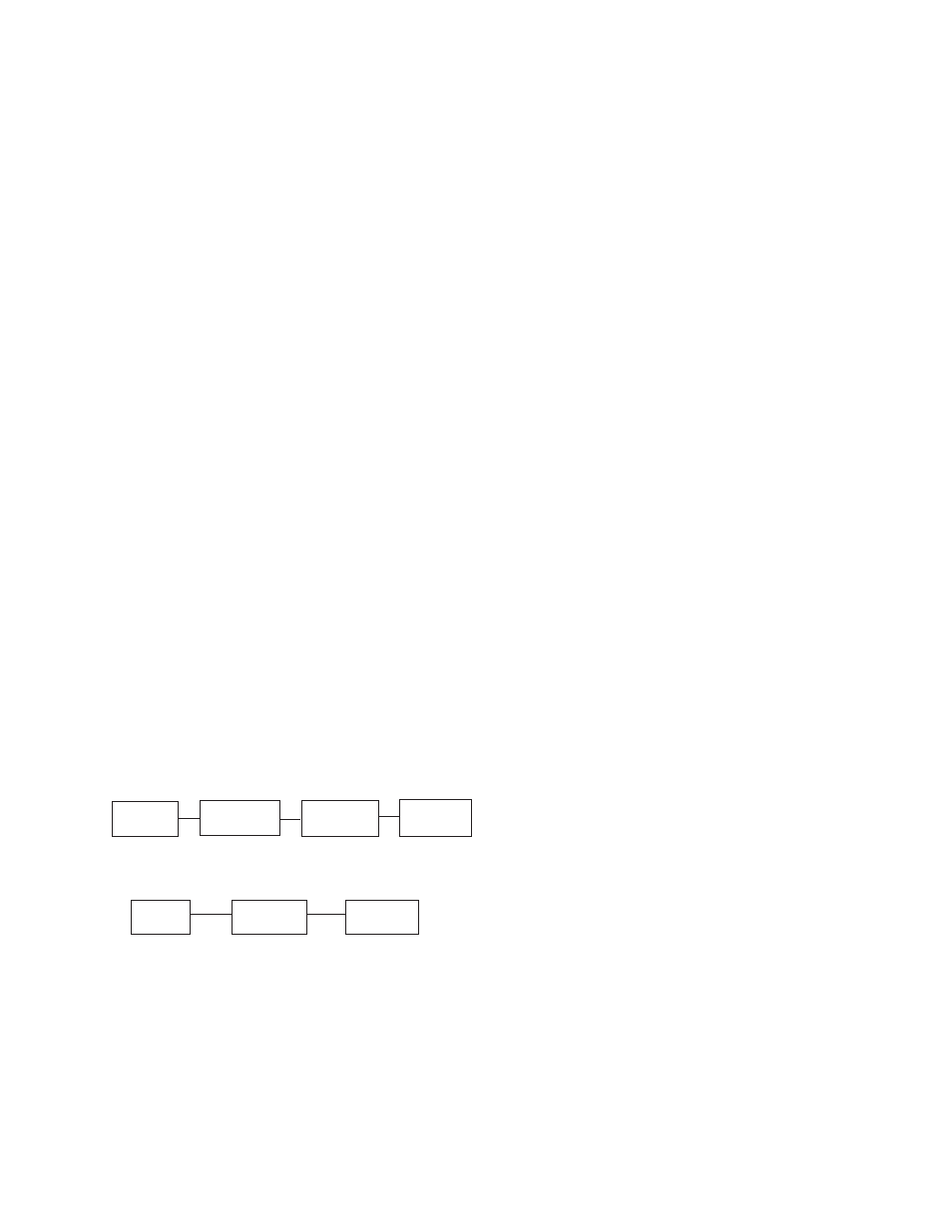
tem. Shown below is a block diagram of a typical L.P. or
N.G. Installation.
Supply
Primary
Secondary
Generator
Tank
Regulator
Regulator
Set
1 2
3
4
TWO (2) REGULATOR FUEL SYSTEM
Supply
Primary
Generator
Tank
Regulator
Set
1
2
4
SINGLE REGULATOR FUEL SYSTEM
Reference numbers 1 through 3 in the block diagrams
above are fuel lines supplied by customer.
Reference number 4 is the engine generator set.
Below is a table of the fuel pressure reading at each ref-
erence in the system.