Setup & installation – WaterChef U9000 User Manual
Page 9
www.waterchef.com
SETUP & INSTALLATION
7
STEP
Red Tubing
Compression Nut
Compression Nut
3/8” T-Valve
Cold Water
Supply Line
Cold Water
Supply Line
Red Tubing
(from 3/8” T-Valve)
Red Inlet Connector
Blue Outlet Connector
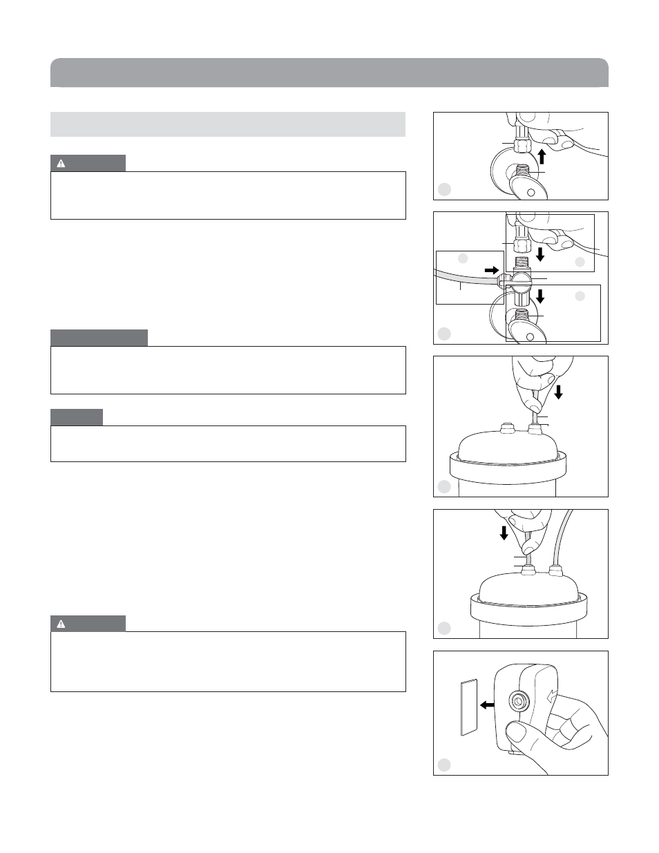
1. Locate an area under the kitchen sink to place the Base. Base should
be located directly under area where the Faucet will be installed.
2. Using the open ended wrench, unthread the compression nut
located on top of the shut-off valve located on existing cold water
supply line.
(fig. L)
3. Thread the 3/8” T-Valve onto cold water supply line, and tighten
with the open ended wrench.
(fig. M, Step 1)
Next, thread the
compression nut onto the top of T-Valve and tighten.
(fig. M, Step 2)
Lastly, press the Red Tubing into the Outlet Connector located
on the T-Valve.
(fig. M, Step 3)
4. Press opposite end of Red Tubing into Red Inlet Connector located
on top of Lid Assembly.
(fig. N)
Then press Blue Tubing into
Blue Outlet Connector.
(fig. O)
5. Locate an area on cabinet wall to mount the Intelligent Monitor
™
.
Secure Intelligent Monitor
™
to the wall using the Velcro Adhesive
Strips provided.
(fig. P)
(continued on following page)
Blue Tubing
Velcro Strip
(on cabinet wall)
Intelligent
Monitor
™
System Installation:
IMPORTANT
Before attempting this installation, be certain to turn “OFF” the cold water supply
located under your sink. If a shut-off valve is not located on the cold water line directly
under your kitchen sink, shut off the main water supply to your home.
RECOMMENDATION
You may want to reduce the length of the Tubing if you find there is excess. However,
it is advisable to leave the Red and Blue Tubing long enough so that the System can
be easily removed from under the sink for Filter Cartridge replacement.
CAUTION
Use a sharp knife when cutting Tubing. Take extra care not to distort Tubing while
cutting. Cut Tubing end straight. Failure to do so may result in leaking.
L
M
3
STEP
2
STEP
1
N
O
P
IMPORTANT
Once inserted completely, give Tubing a gentle tug to make sure it has been properly
seated in the fitting to create a permanent seal. If you find that it is necessary to
remove the Tubing from Inlet or Outlet Connectors, depress the small Collar located
on the Inlet and Outlet Connectors and pull Tubing upward at same time.