Assembly (continued), Locating stove, Vogelzang international corp – Vogelzang TR001B User Manual
Page 6
Page 6
|
DEFENDER™
Vogelzang International Corp.
TR001B | 20120125.0
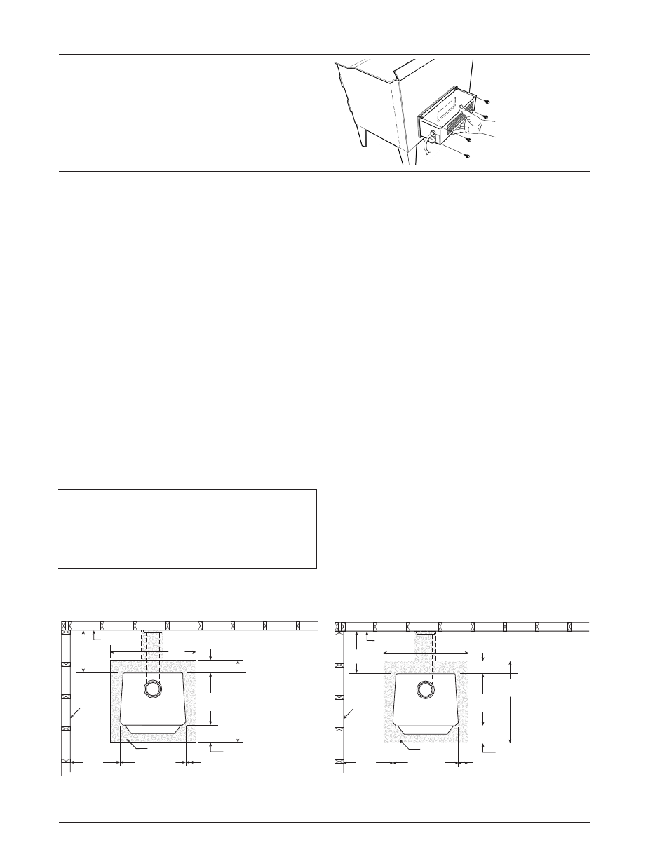
Fig. 6 – Top View Minimum Clearance Dimensions
from Combustible Surfaces
1. The stove must be placed on solid concrete, solid
masonry, or when installed on a combustible floor,
on an listed UL 1618 Type 2 floor protector, such
as Hy-C or Imperial Model UL 3648BK (US) or
UL4048BK (CAN) or equivalent. Floor protector
must be
1/2˝/13mm minimum thickness (“k” value
= 0.84, R value = 0.59, see page 23 for calculation
formulas) non-combustible material or equivalent.
US Requirements: The floor protector must extend
at least 16˝/41cm beyond the front of the access
door, 6˝/15.2cm to the sides, 12˝/30.5cm beyond the
rear and must extend under and 2˝/51mm beyond
either side of the stove pipe connector if it is el-
bowed towards a wall. (See figures 6–8 and consult
local building codes and fire protection ordinances.)
Canadian Requirements: The base must extend
at least 18˝/46.8cm beyond the front of the access
door, 8˝/20.3cm to the sides, 8˝/20.3cm behind the
stove and must extend under and 2˝/51mm beyond
either side of the stove pipe if it is elbowed towards
a wall. (See figures 6–8 and consult local building
codes and fire protection ordinances).
CAUTION: (FIRE HAZARD) CARPETING AND
OTHER COMBUSTIBLE MATERIAL SHALL
NOT COVER THE FLOOR PROTECTOR. THESE
MATERIALS MUST REMAIN OUTSIDE OF
COMBUSTIBLE CLEARANCES, SEE FIG. 6 – 8.
ASSEMBLY (continued)
continued on next page
2. The room in which he stove is installed must have
a minimum floor to ceiling height of 8 ft./2.4 m & a
minimum stove top to ceiling height of 55˝/140 cm.
3. The stove must have its own flue. Do not con-
nect this unit to a chimney flue serving other
appliances.
4. After observing the clearances to combus-
tible materials (figures 6–8), locate your floor
protector accordingly (figure 6) and careful-
ly place the stove in your selected location.
Install stove pipe, elbows, and thimble as
required, utilizing either a recently cleaned and
inspected 6˝/152mm masonry chimney or a
6˝/152mm i.d. UL 103 HT (US)/ULC-S629 (CDN)
listed manufactured chimney.
5. Use round 6˝/152mm dia., minimum 24 MSG black
or 26 MSG blue steel stove pipe to connect the
stove to the chimney. DO NOT USE GALVANIZED
DUCT PIPE AS A CONNECTOR. Secure pipe
sections with three (3) sheet metal screws no more
than a maximum of 3˝/76mm apart in each stove
pipe and/or elbow joint to firmly hold the pipe sec-
tions together. DO NOT CONNECT THIS STOVE
TO ANY AIR DISTRIBUTION OR DUCT SYSTEM.
6. R e c h e c k c l e a r a n c e s f r o m t h e s t o v e ,
connector stove pipe, and corner clearanc-
es using the illustrations in figures 6–8 and
2. Route the power cord away from stove. Do not
allow the power cord to touch any hot surfaces. Keep
power cord at least 12˝ from stove surfaces.
3. Once stove is positioned, plug power cord into a
grounded 120v outlet.
Fig. 5 – Mount
Blower Assembly to
rear Heat Deflector
LOCATING STOVE
FLOOR
PROTECTOR
DASHED LINES SHOW HORIZONTAL CHIMNEY CONNECTOR
AND ADDITIONAL FLOOR PROTECTOR REQUIRED BENEATH
AND EXTENDING 2"/5cm BEYOND EACH SIDE
COMBUSTIBLE CONSTRUCTION IN ACCORDANCE WITH US NFPA 211
BACKWALL
SIDEWALL
8"/20.3cm
minimum
18"/46.8cm
44"/112cm
18"/46.8cm min.
8"/20.3cm min.
23"/54.5cm
15"/38.1cm
min.
12"/30.5cm
minimum
TOP VIEW | CANADIAN CLEARANCES
39"/
100cm
TR001B
Minimum
Clearances &
Minimum
Floor Protector
Dimensions
for Canadian
Installation
According to
ULC 5627
FLOOR
PROTECTOR
DASHED LINES SHOW HORIZONTAL CHIMNEY CONNECTOR
AND ADDITIONAL FLOOR PROTECTOR REQUIRED BENEATH
COMBUSTIBLE CONSTRUCTION IN ACCORDANCE WITH NFPA 211
BACKWALL
SIDEWALL
35"/
89cm
TR001B
18"/45.7cm
AND EXTENDING 2"/5cm BEYOND EACH SIDE
TOP VIEW | USA CLEARANCES
12"/30.5cm
minimum
12"/30.5cm
minimum
46"/117cm
Minimum
Clearances &
Minimum
Floor Protector
Dimensions
for United States
Installation
According to
UL 1482-2006
23"/54.5cm
15"/38.1cm
min.
6"/15.2cm min.
16"/40.6cm min.