Viconics H270 User Manual
Page 7
Viconics Electronics Inc.
9245, Langelier Blvd, St-Leonard, Quebec, Canada H1P 3K9
www.viconics.com
LIT-H270X-E03 H270.doc
7
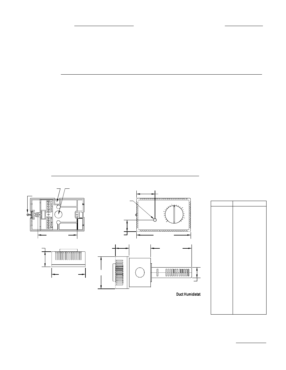
"Autocal" button
(Invisible)
1.00" [25mm]
1.275" [32mm]
Cover
1.275" [32mm]
2.8" [71mm]
2.8" [71mm]
3.275" [83mm]
Wiring from top
Security screw
Base
Wiring from back
2.0" [50.8mm]
3.77" [95.8mm]
Cover
0.9" [22.8mm]
1.60" [41mm]
4.5" [114mm]
AUTOCAL PROCEDURE
1.
Measure the room humidity near the Viconics humidistat
with an accurate hygrometer.
2. Turn the humidistat set point dial to match the reading of
the hygrometer.
3. Push and hold the Autocal button for more than 3
seconds or until the internal red light turns On and Off.
SENSOR FAILURE PROTECTION
The sensor is the most sensitive part of the humidistat and
also the most exposed. In the case of a sensor failure in
humidification mode, the H200 will automatically assume a
failsafe output of 0%.
SPECIFICATIONS
Operating Conditions: 5 °C to 50 °C ( 32 °F to 122 °F )
•Control:
0% to 95% R.H. non-condensing
•Sensor:
0% to 100% R.H. (see Note 1.)
Resolution:
± 0.1 %
Repeatability:
0.5 %
Accuracy and sensor interchangeability:
± 2 % R.H. from 0 to 100 % R.H.
Range:
10 % to 90 % R.H. for 5 to 50 °C
(41 °F to 122 °F )
Temperature effect:
0.05 % / °F
Outputs:
Isolated Triac: 30 Vac at ½ A max.*
0 to 5 VDC into 1K
Ω resistance min.
0 to 10 VDC into 2K
Ω resistance min.
0/5 VDC at 20 mA max.for both outputs
Power:
24 VAC -15%, +10%; 50/60 Hz; 2 VA
Base and casing:
Off-white; self extinguishing
ABS plastic
* Triac outputs can only switch AC loads. Use relays when
switching dc loads.
Note 1. Humidity sensor: Solid state humidity sensor.
Suitable for normal, clean air. Not to be used in corrosive
or harmful environment.
DIMENSIONS
Note: Specifications and equipment are subject to change without prior notice.
TABLE 5:
SENSOR
CHARACTERISTICS
Voltage between black and white
wire, terminals #6 and #7
HUMIDITY
SENSOR OUTPUT
0 %
1.05 V
5 %
1.19 V
10 %
1.34 V
15 %
1.48 V
20 %
1.63 V
25 %
1.77 V
30 %
1.92 V
35 %
2.06 V
40 %
2.20 V
45 %
2.35 V
50 %
2.49 V
55 %
2.64 V
60 %
2.78 V
65 %
2.93 V
70 %
3.07 V
75 %
3.21 V
80 %
3.36 V
85 %
3.50 V
90 %
3.65 V
95 %
3.79 V
100 %
3.94 V
Fig.9: Dimension drawing