Wiring diagram, Hp727-s control board, Instrument wiring diagram – Viconics HP727S User Manual
Page 5
5
5
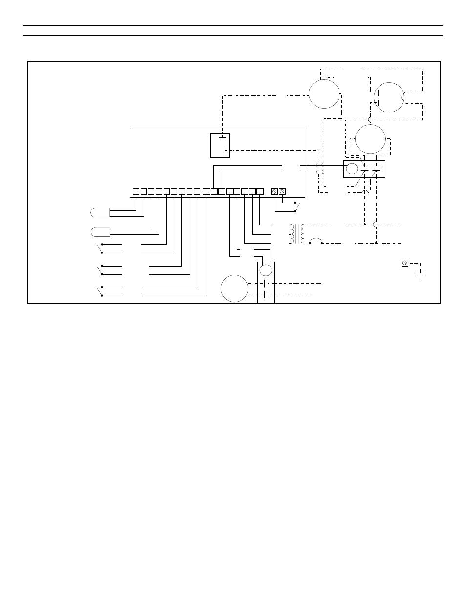
5. INSTRUMENT WIRING DIAGRAM
1 2 3 4 5 6 7 8 9 10
13 14 15 16 17
11 12
Black
12 Vac
0 Vac
24 Vac
Red
FAN
COMPRESSOR
C
R
S
White
Brown
Herm.
Brown
Black & White
F
C
RLY1
HP727-S
Control Board
L1
L2
L1
L2 or Neutral
Black
Black
Light Blue
Light Blue
Purple
Purple
Blue
Blue
Yellow
Yellow
Water sensor
Defrost sensor
High pressure switch
Closed = OK
Opened = high pressure
Low pressure switch
Closed = OK
Opened = low pressure
Flow switch
Closed = flow
Opened = no flow
Remote switch
Pool (opened)
Spa (closed)
Wiring Diagram
Wiring727.dsf
Orange (240 Vac)
or
Red (208 Vac)
FILTER
PUMP
24 Vac compressor
contactor
24 Vac filter
pump contactor
CAP
24 Vac transformer
Ground
208 / 240 Vac
50 / 60 Hz
See also other documents in the category Viconics For Home:
- VTR8300 Line Voltage Application Guide (23 pages)
- VTR8300 Line Voltage Installation Guide (7 pages)
- VTR8300 Line Voltage User Interface Guide (32 pages)
- VC3000 Line Voltage Installation Guide (8 pages)
- VT8300 Low Voltage Installation Guide (13 pages)
- VT8300 Low Voltage Application Guide (64 pages)
- VT8300 Low Voltage User Interface Guide (45 pages)
- VT8000 Series Device Replacement Guide (7 pages)
- VT8600 Series BACnet Integration Guide (41 pages)
- VT8600 Installation Guide (12 pages)
- VT8600 User Interface Guide (47 pages)
- VT7657 BACnet Integration Guide (First Release 1000 Series) (23 pages)
- VT7657 BACnet Integration Guide (Current Release 5000 Series PIR Ready) (29 pages)
- VT7657 Echelon Integration Guide (22 pages)
- VT7657 Installation Manual (36 pages)
- VT7000 Series Installation Guide (2 pages)
- VT7000 Series Application Guide (27 pages)
- VT8000 Series Uploader Tool (5 pages)
- VT7600 Installation Guide (First Release 1000 Series) (24 pages)
- VT7600 Installation Guide (Current Release 5000 Series PIR Ready) (39 pages)
- VT7600 Echelon Integration Manual (22 pages)
- VT7000 Series PIR cover Installation Guide (2 pages)
- VT7000 Series PIR Application Guide (11 pages)
- VT7682S Application Guide (17 pages)
- VT7682S Installation Manual (19 pages)
- VT7606E Installation Manual (34 pages)
- VT7600W Installation Manual (35 pages)
- VT7600F Installation Manual (29 pages)
- VT7300 Installation Manual (First Release 1000 Series) (17 pages)
- VT7300 Installation Manual (Previous Release 5000 Series PIR Ready) (17 pages)
- VT7300 Installation Manual (Current Release 5000 Series PIR Ready) (33 pages)
- VT7300 (BACnet) Integration Manual (31 pages)
- VT7300 (Echelon) Integration Manual (27 pages)
- VT7300F-2572 Installation Manual (26 pages)
- VT7200 Installation Manual (First Release 1000 Series) (15 pages)
- VT7200 Installation Manual (Previous Release 5000 Series PIR Ready) (15 pages)
- VT7200 Installation Manual (Current Release 5000 Series PIR Ready) (29 pages)
- VC3000 Installation Manual (10 pages)
- VTR7300 Installation Manual (25 pages)
- VTR7300 Application Manual (28 pages)
- VWA5000W Installation Guide (18 pages)
- VCM7000 Installation Guide (4 pages)
- VWZS Application Guide (40 pages)
- VWZS Integration Guide (70 pages)
- VWZS Engineering Guide Specifications (10 pages)