Viconics VCM7000 Installation Guide User Manual
Page 3
VCM7000 Series-Installation Guide
3 |
i
nstallation
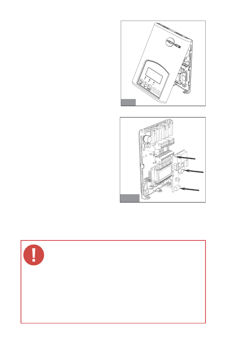
Remove the security screw on the bottom of
Terminal Equipment Controller cover.
• Open unit by pulling on the bottom
side of Terminal Equipment Controller
(fig. 1).
• Remove power to the unit by
disconnecting to top left terminal block.
• Ensure power is down by confirming
the local display is not operating.
Module Installation
1. Align module connector and the 2
retaining pins on their respective
insertion points of the controller base.
2. Insert connector and the 2 retaining
pins all at once by pressing on the 3
location simultaneously. (fig. 2).
3. Make sure retaining pins are properly
snapped in place.
4. A misalignment of the module
connector while the controller is
powered may permanently damage
the Terminal Equipment Controller or
the communication module
5. Power back the unit by reconnecting
the top left terminal block.
6. Re-install the cover (top side first)
7. Re-install security screw
Fig. 2
Fig. 1
• Electronic controls are static sensitive devices. Discharge yourself properly
before manipulating and installing the Terminal Equipment Controller.
• A misalignment of the module connector while the controller is powered
may permanently damage the Terminal Equipment Controller or the
communication module.
• All VT(R)7000 series controls are designed for use as operating controls
only and are not safety devices. These instruments have undergone rigorous
tests and verification prior to shipping to ensure proper and reliable operation
in the field. Whenever a control failure could lead to personal injury and/or
loss of property, it becomes the responsibility of the user / installer / electrical
system designer to incorporate safety devices ( such as relays, flow switches,
thermal protections, etc…) and/or alarm systems to protect the entire system
against such catastrophic failures. Tampering with the devices or unintended
application of the devices will result in a void of warranty.