Viconics VT7200 Installation Manual (First Release 1000 Series) User Manual
Page 7
7
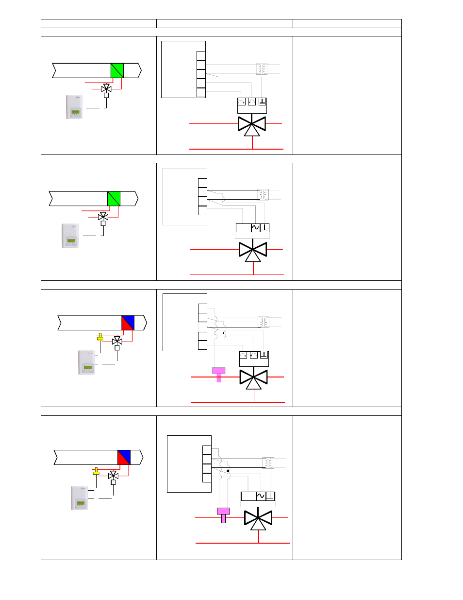
Schematic Wiring Settings
Heating or cooling hydronic valve control ( VT7200C1000 ) Floating actuator
Mandatory
• Out1Conf = 2.0
• CntrltTyp = Floating
• FL time = as per actuator
If cooling only set::
• SeqOpera = 0 Cooling only
If heating only set::
• SeqOpera = 1 Heating only
Heating or cooling hydronic valve control ( VT7200F1000 ) Analog actuator
Mandatory
• Out1Conf = 2.0
• RA/DA = as per actuator
If cooling only set::
• SeqOpera = 0 Cooling only
If heating only set::
• SeqOpera = 1 Heating only
Cooling / heating with changeover hydronic valve control ( VT7200C1000 ) Floating actuator
Mandatory
• Out1Conf = 2.0
• CntrltTyp = Floating
• FL time = as per actuator
If heat / cool auto-changeover
with a local water temperature
sensor set:
• SeqOpera = 0 Cooling only
• UI3 = COS
Cooling / heating with changeover hydronic valve control ( VT7200F1000 ) Analog actuator
Mandatory
• Out1Conf = 2.0
• RA/DA = as per actuator
If heat / cool auto-changeover
with a local water temperature
sensor set:
• SeqOpera = 0 Cooling only
• UI3 = COS
UI3 COS
0 V~ Com
24 V~ Hot
BO1 Open
BO2 Close
Modulating Floating
Valve Cooling or Heating
Room Temperature
Control Thermostat
Analog Valve
Cooling or Heating
Room Temperature
Control Thermostat
0 to 10
Vdc
UI3 COS
0 V~ Com
24 V~ Hot
AO1
Modulating Floating Valve
Heating and/or Cooling
Optional Water
Supply Sensor
Room Temperature
Control Thermostat
Supply water
temperature sensor
UI3 COS
0 V~ Com
24 V~ Hot
BO1 Open
BO2 Close
Analog Valve
Heating and/or Cooling
Optional Water
Supply Sensor
Room Temperature
Control Thermostat
Supply water
temperature sensor
0 to 10
Vdc
UI3 COS
0 V~ Com
24 V~ Hot
AO1