Viconics VT7200 Installation Manual (First Release 1000 Series) User Manual
Page 15
15
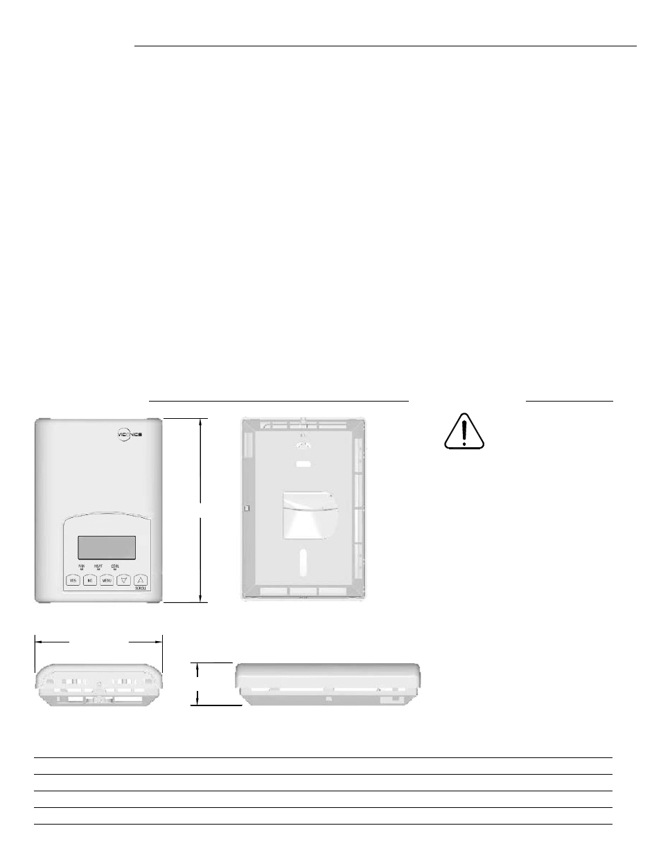
3.38" [86 mm]
1.13" [29 mm]
4.94" [125 mm]
Specifications
Thermostat power requirements: 19-30 Vac 50 or 60 Hz; 2 VA Class 2
Operating conditions: 0 °C to 50 °C ( 32 °F to 122 °F )
0% to 95% R.H. non-condensing
Storage conditions: -30 °C to 50 °C ( -22 °F to 122 °F )
0% to 95% R.H. non-condensing
Sensor: Local 10 K NTC thermistor
Resolution: ± 0.1 °C ( ± 0.2 °F )
Control accuracy: ± 0.5 ° C ( ± 0.9 °F ) @ 21 °C ( 70 °F ) typical calibrated
Occupied and unoccupied setpoint range cooling: 12.0 to 37.5 °C ( 54 to 100 °F )
Occupied and unoccupied setpoint range heating: 4.5 °C to 32 °C ( 40 °F to 90 °F )
Room and outdoor air temperature display range -40 °C to 50 °C ( -40 °F to 122 °F )
Proportional band for room temperature control: Cooling & Heating: 1.8°C ( 3.2°F )
Binary inputs: Dry contact across terminal BI1, BI2 & UI3 to Scom
Contact output rating: Triac output: 30 Vac, 1 Amp. Maximum, 3 Amp. in-rush
Analog: 0 to 10 Vdc into 2K
Ω resistance min.
Wire gauge 18 gauge maximum, 22 gauge recommended
Dimensions: 4.94”
x 3.38” x 1.13”
Approximate shipping weight: 0.75 lb ( 0.34 kg )
Agency Approvals:
UL
UL 873 (US) and CSA C22.2 No. 24 (Canada), File E27734 with
CCN XAPX (US) and XAPX7 (Canada)
FCC
Compliant to CFR 47, Part 15, Subpart B, Class A (US)
Industry Canada
ICES-003 (Canada)
CE
EMC Directive 89/336/EEC (Europe Union)
C-Tick
AS/NZS CISPR 22 Compliant (Australia / New Zealand)
Supplier Code Number N10696
Drawing & dimensions
Fig.13 – Thermostat dimensions
Important notice
All VT7200 series
controls are for use as
operating controls only
and are not safety
devices. These instruments have
undergone rigorous tests and
verifications prior to shipment to ensure
proper and reliable operation in the field.
Whenever a control failure could lead to
personal injury and/or loss of property, it
becomes the responsibility of the user /
installer / electrical system designer to
incorporate safety devices ( such as
relays, flow switch, thermal protections,
etc…) and/or alarm system to protect
the entire system against such
catastrophic failures. Tampering of the
devices or miss application of the device
will void warranty.
Notes: