Electrical connections – VICI D-4-I User Manual
Page 20
16
Electrical Connections
CAUTION: Do not use a wrench to tighten the SMC con-
nectors on the bias and electrometer cables.
Connections should be finger tight only.
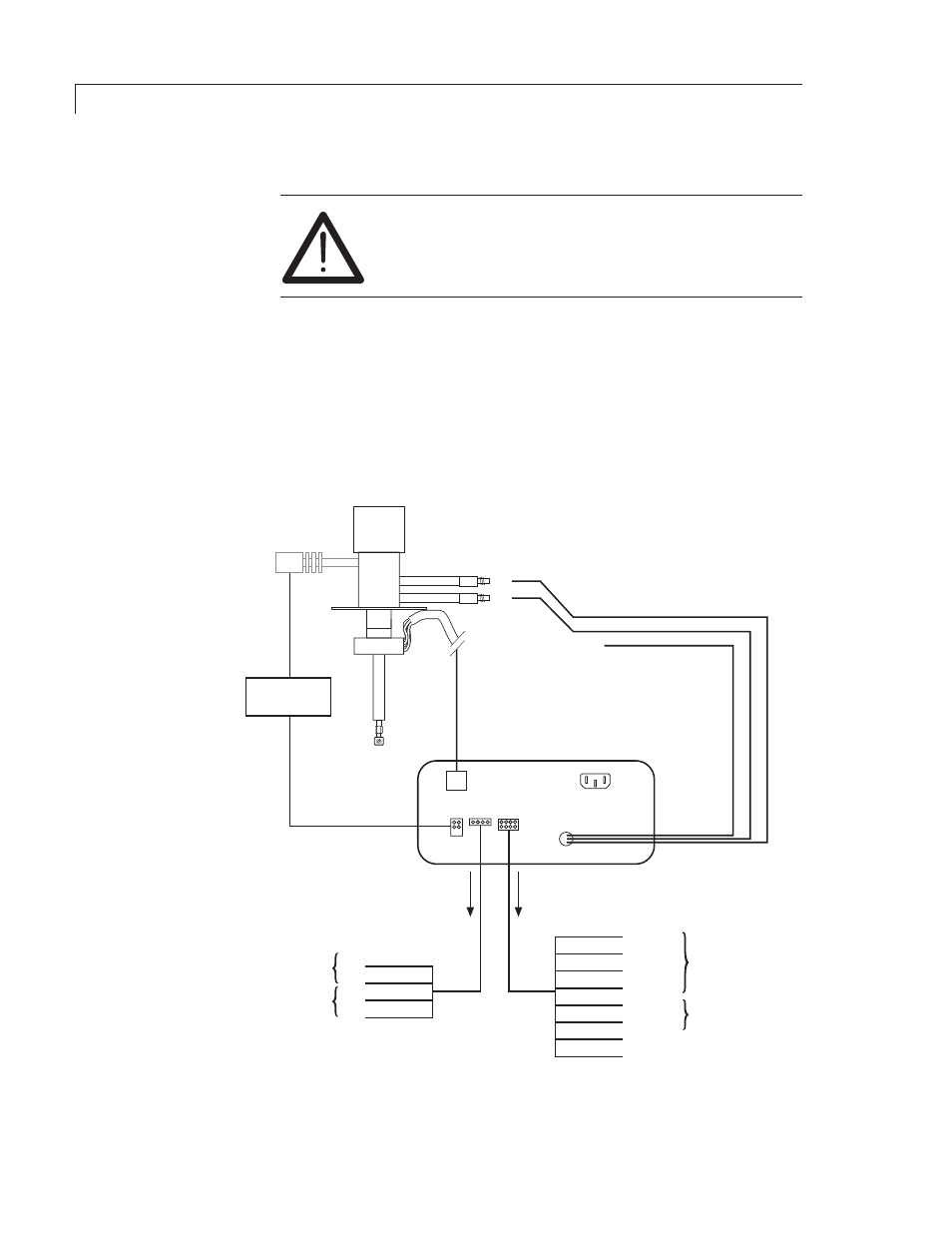
1. Referring to
Figure 4 as necessary, connect BIAS-B cable to the top
electrode and the electrometer cable (
ELECT) to the bottom electrode.
The
BIAS-A remains disconnected.
2. Connect the high-voltage cable from the detector to the pulse supply, and
connect the pulse supply cable between the back of the controller and
the pulse supply. Connect the heater cable from the detector to the back
of the controller.
CONTROLLER
(Rear panel)
HEATER CABLE
FROM DETECTOR
PULSER
MODULE
HIGH
VOLTAGE
ELECTROMETER
BIAS-A
BIAS-B
RED
BLACK
WHITE
GREEN
BROWN
BLUE
ORANGE
YELLOW
RED
BLACK
GREEN
WHITE
0 - 10 V
Common
0 - 1 V
Shield
COM
SET
UNATTENUATED
OUTPUT
AUTO
ZERO
TO COMPUTER
OR INTEGRATOR
+
ATTENUATED
OUTPUT
SHIELD
TO
RECORDER
(no connection)
Figure 4: Electrical connections
Installation
If your controller rear
panel does not look like
this, refer to page 23 in
the Appendix.