VICI D-4-I User Manual
Page 17
13
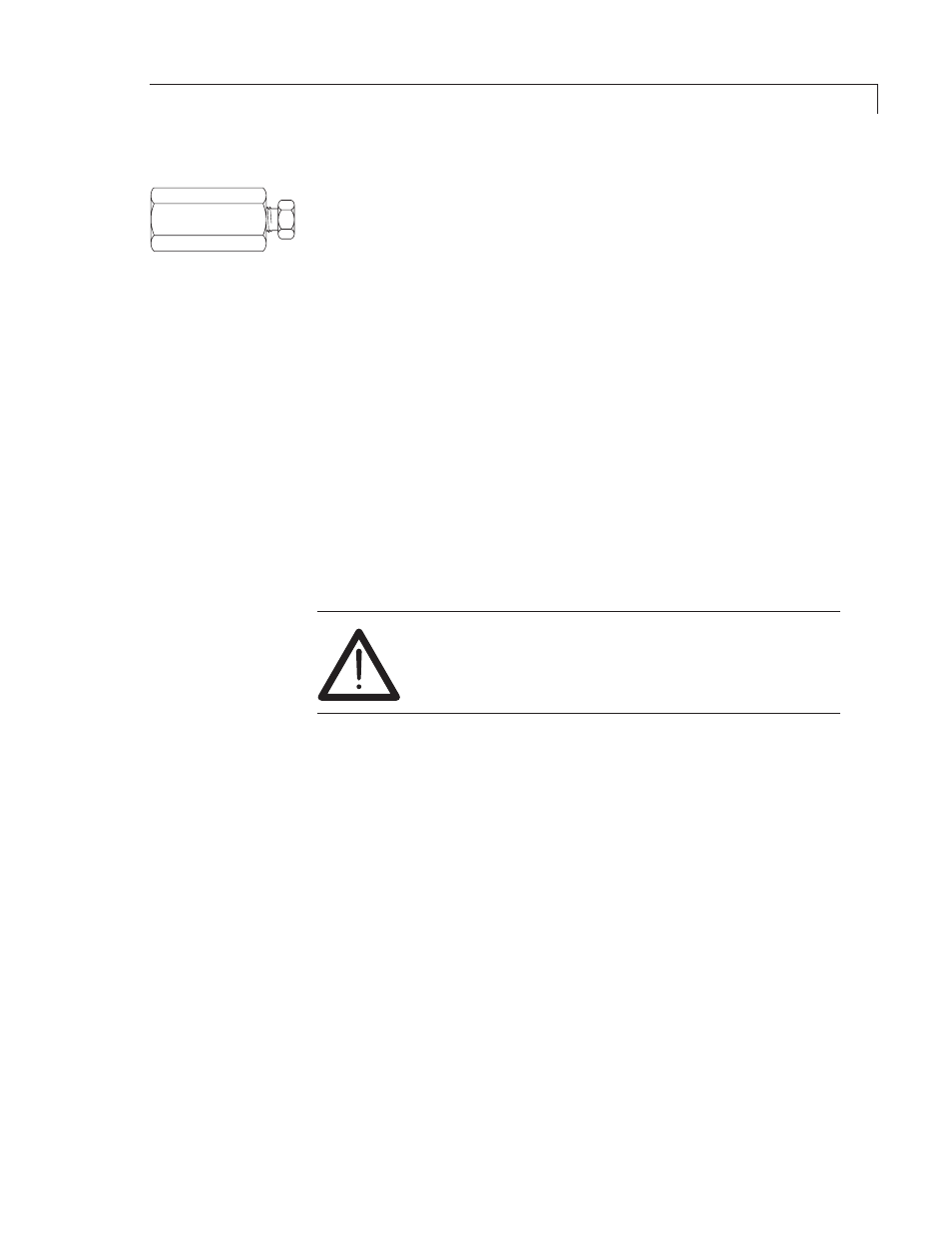
EZR21
Installing and Purging the Helium Purifier
1. If the pressure regulator has a 1/8" male cone-type outlet port, install
the Valco 1/8" external to 1/16" internal reducer (EZR21); if it has a
1/4" male cone-type outlet port, install the Valco 1/4" external to 1/16"
internal reducer (EZR41). For other regulator outlet fittings, a wide
variety of Valco adapters is available.
2. Remove the cap from the inlet tube of the Valco helium purifier and insert
the tube fitting into the 1/16" reducer port. (Keep the outlet tube capped.)
Use a 1/4" wrench to turn the nut one-quarter turn past the point where
the ferrule first starts to grab the tubing. Do not remove the fitting. When
made up properly, it should be leak-tight.
3. Turn the output pressure regulating knob clockwise until the gauge
registers 345 KPA (50 psi).
4. Allow five minutes for equilibration, then turn the regulating knob all the
way counterclockwise.
5. Observe the needle of the output pressure gauge for 15 minutes. There
will be a slight initial drop, but if it doesn’t move after that, consider that
all the connections are tight.
6. If necessary, use an electronic leak detector to locate any leaks. If a
leak detector is not available, tighten all the fittings (including the output
pressure guage), and repressurize the system for another test.
CAUTION: Never use leak detecting fluids on any
part of this system.
7. Upcap the outlet tube of the purifier and purge the system for
15 to 30 minutes at 60 - 80 mL/min to eliminate air from the purifier
getter material.
Connecting the Discharge Gas to the Detector
1. If you are supplying the GC from the helium purifier, use the Valco tee
(ZT1). Otherwise, use one of the Valco 1/16" unions (ZU1) to connect
the outlet tube of the purifier to the inlet of the supplied discharge gas
restrictor (TGA-R-30F60P).
2. Connect the outlet end of the restrictor to a flow measuring device and
adjust the helium pressure to obtain a flow of ~30 mL/min.
3. After setting the flow rate, connect the outlet of the restrictor to the dis-
charge gas inlet tube at the top of the detector.
Installation