Table 2 – USL UPC-2 User Manual
Page 7
UPC-1/UPC-2 Installation Manual
7
January, 1999
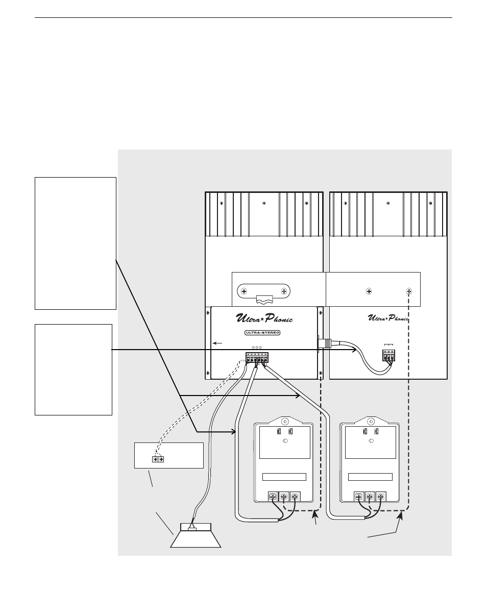
FOR THE UPC-2
(See Figure E) Connect one of the two IRP-20 AC Power Packs to the IRC-20 AC Panel #1
terminals, and the second IRP-20 to the AC Panel #2 terminals using standard 18-gauge
or greater zip cord. (See Table 2 for lengths.) Make sure there are no loose wire strands
that could touch any nearby metal and short the Power Pack.
DO NOT SHORT THE POWER SUPPLY.
Connect each Power Pack to a 115 V AC 50/60 Hz outlet.
+ –
AC
PANEL
#1
PANEL
#2
AC
50
%
CLIP
INPUT
LEVEL
ADJUST
POWER
CARRIER
INPUT
(95kHz)
DC
POWER
(Nom. 28v)
H
–
+
INFRA-RED TRANSMISSION SYSTEM
MODEL IRE-10 EMITTER PANEL
Processor Center Channel
OR
Center Channel Speaker
+ E
®
INFRARED HEADPHONE TRANSMISSION SYSTEM
MODEL IRC-20 EMITTER/MODULATOR SYSTEM
IRM-20 MODULATOR
ULTRA
★
STEREO LABS, INC.
•
Tarzana, California
®
Connect ground wires to
IRM-20 & IRE-10 Chassis
(May be required by local
building code).
AC Gnd AC
AC Gnd AC
AC Power Pack
AC Power Pack
Fig. E
Connecting the
audio input and
both 24 V AC
power packs with
the UPC-2 system
This cable must be
3-conductor.
White = H
Red
= +
Black = –
See Table 2 above
for maximum
lengths and
gauges.
TABLE 2
Maximum lengths
and gauge sizes for
connector cord from
IRP-20 AC Power
Packs to the IRC-20
AC Panel #1 and #2
terminals.
50'
@
18 ga.
70'
@
16 ga.
100'
@
14 ga.
150'
@
12 ga.