Upc features – USL UPC-2 User Manual
Page 4
UPC-1/UPC-2 Installation Manual
4
January, 1999
+ –
AC
PANEL
#1
PANEL
#2
AC
50
%
CLIP
INPUT
LEVEL
ADJUST
POWER
®
INFRARED HEADPHONE TRANSMISSION SYSTEM
MODEL IRC-20 EMITTER/MODULATOR SYSTEM
IRM-20 MODULATOR
ULTRA
★
STEREO LABS, INC.
•
Tarzana, California
®
5
1
4
2
3
6
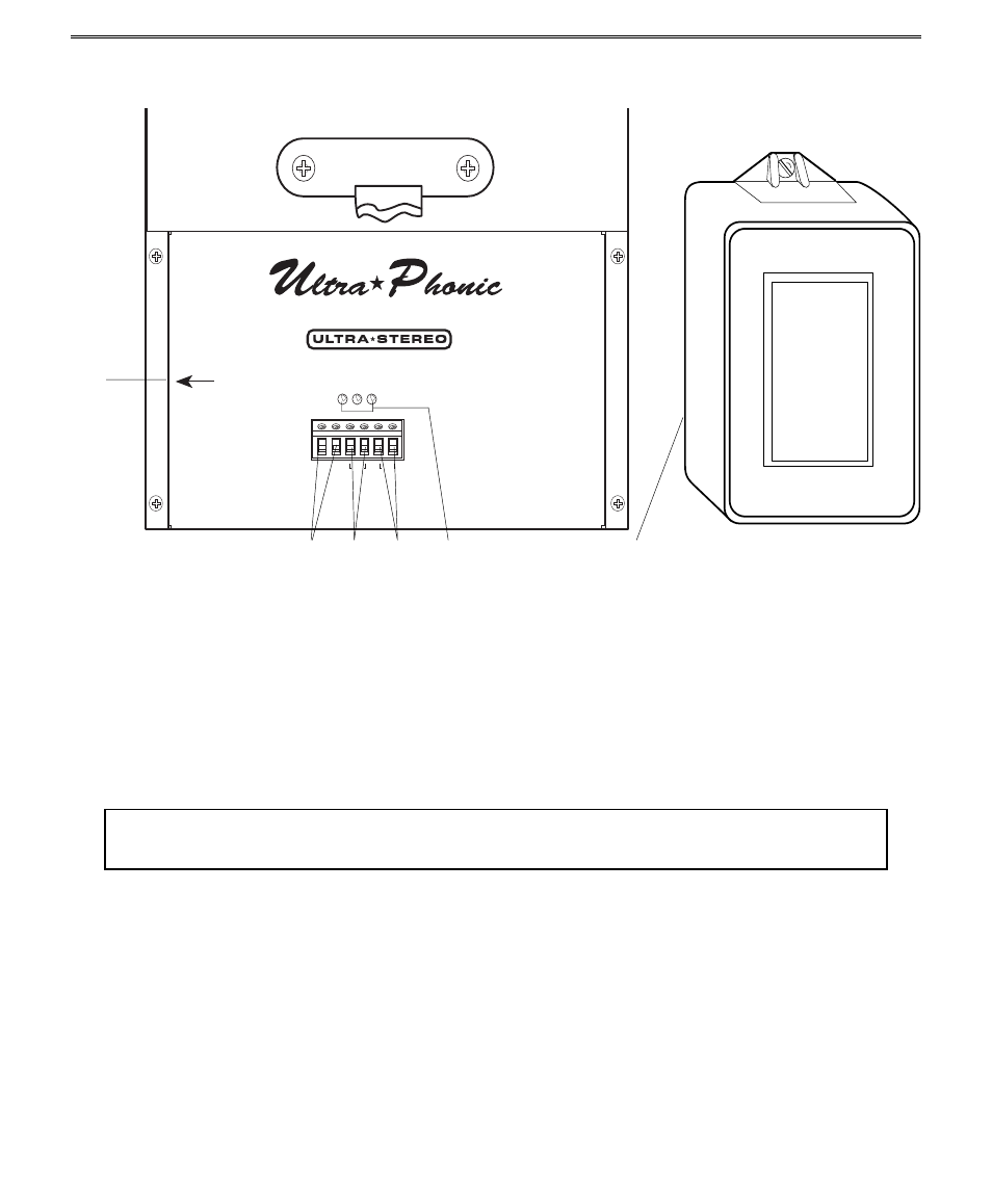
Fig. A – Rear view of the IRC-20 showing connections and
indicators
Fig. B – IRP-20 AC Power Pack
UPC FEATURES
1. AUDIO INPUT
The IRC-20 will accept an audio signal level from 100 mv to greater
TERMINALS
than 30 V rms.
2. AC PANEL #2
Connects to the 24 V AC Power Pack supplied with the IRC-20. For
use only with two-panel systems. See page 7.
3. AC PANEL #1
Connects to the 24 V AC Power Pack supplied with the IRC-20. See
page 6.
WARNING! Use only the AC Power Pack supplied with the IRC-20 or else permanent
damage to the unit may result.
4. LED INDICATORS
From left to right, the ‘CLIP’ LED illuminates when the input level
overloads the IRC-20. The ’50%’ LED indicates that the input level
reaches 50% modulation. It will just illuminate when the input level is
correctly set. The ‘POWER’ LED indicates that the unit is on.
5. INPUT LEVEL TRIMPOT
This 15-turn trimpot adjusts the input signal level.
6. 24 V AC IRP-20
Connect to the AC PANEL #1 terminals. If you have a two-panel
system, you need two power packs.
Newer transformers have a resetting fuse in the form of an internal
poly switch. In this instance, an external fuse is not required.