Cm series rear panel – USL CM-Series (8 Channel) User Manual
Page 7
1
15V
230V
- 6 -
CM Series
I
NSTRUCTION
M
ANUAL
Ultra Stereo Labs, Inc.
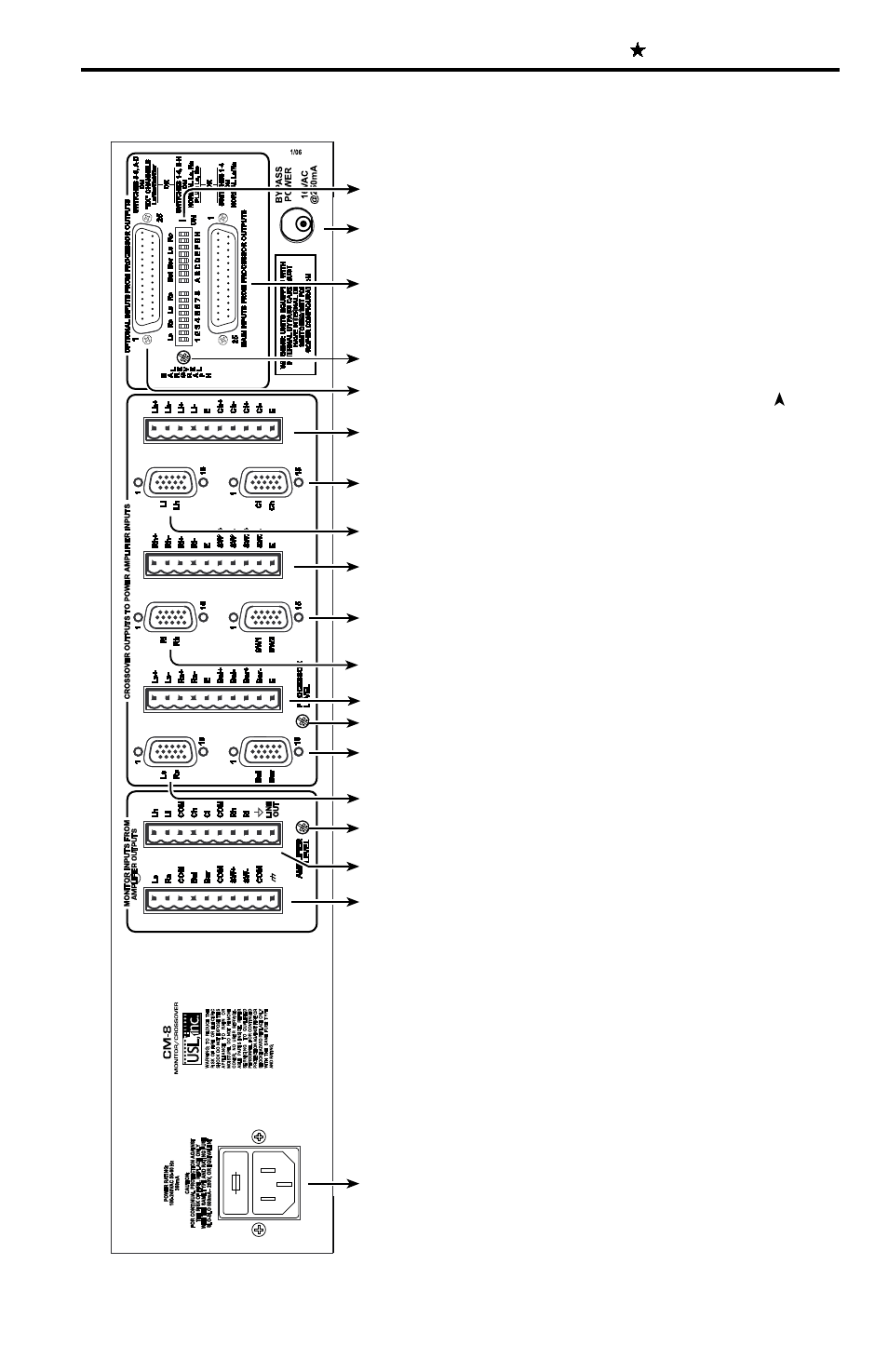
CM Series Rear Panel
1. Main AC connector with fuse.
2. Amplifier outputs - connect to the power amplifier speaker o
utputs corresponding to Ls, Rs, Bsl, Bsr and Sw channels.
3. Amplifier outputs - connect to the power amplifier speaker o
utputs corresponding to Lh, Ll, Ch, Cl and Rh, Rl.
4. Amplifier level - this trimpot adjusts the level of the inpu
t lines coming from the Power Amplifiers.
5. HD-15 connector - connect to Ls/Rs amplifier
.
6. HD-15 connector - connect to Bsl/Bsr amplifier
.
7. Processor level - this trimpot adjusts the level of the inpu
t lines coming from the processor
.
8. Crossover outputs - connect to the power amplifier inputs c
orresponding to Ls, Rs, Bsl and Bsr
.
9. HD-15 connector - connect to Rl/Rh amplifier
.
10. HD-15 connector - connect to Sw amplifier
.
1
1. Crossover outputs - connect to the power amplifier inputs cor
responding to Rl, Rh and Sw
.
12. HD-15 connector - connect to Ll/Lh amplifier
.
13. HD-15 connector - connect to Cl/Ch amplifier
.
14. Crossover outputs - connect to the power amplifier inputs co
rresponding to Ll/Lh and Cl/Ch amplifier
.
15. Optional input - connect these to the EX outputs of the proc
essor
16. Bargraph level - this trimpot adjusts the sensitivity of the
front panel VU Bargraph.
17. Main input - connect this to the main outputs of the process
or
.
18. AC Emergency power input - 12-16V
AC, 0.5A
19. Channel configuration DIP
switches. (See Page 1
1)
1
2
3
4
5
6
7
8
9
10
11
12
13
14
15
16
17
18
19
10