TriangleTube TTP Series User Manual
Page 15
applications
13
STEaM To WaTEr aPPlICaTIonS
•
Ensure the braze plate heat exchanger is mounted
vertically to allow gravity drainage of the conden-
sate.
• The installer should use “Good Steam Practices”
which include a steam trap below the unit and vacu-
um breakers.
•
The steam circuit must enter the heat exchanger’s
top connection, with the condensate leaving the heat
exchanger through the bottom connection.
•
Provide steam traps at critical points e.g. in front of
the control valve, to prevent “pooling” of condensate.
Water Hammer and other deformations Caused By
Wet Steam: a high moisture content in the steam
could condense within the heat exchanger forming
pools of water at critical points, exposing the sys-
tem and the heat exchanger to water hammer. one
critical point is the area ahead of the control valve
when the valve is located ahead of the inlet to the
heat exchanger. When the control valve is in the
close position the stationary steam in front of the
valve is subject to condense. Heat losses due to
radiation and/or faulty insulation can increase the
rate of condensation. also, when the control valve
is in the closed position, condensation on the plates
of the heat exchanger occurs, producing a vacuum
or negative pressure inside the heat exchanger.
When the control valve opens to admit steam to the
heat exchanger, the differential in pressure causes a
sudden acceleration in the steam flow, pulling the
accumulated water into the heat exchanger at a high
velocity. The amount of energy produced by this
water at a high velocity can be very great, resulting
in heavy wear and tear and other mechanical dam-
age in the heat exchanger, which results in potential
leaks.
avoidance Practices: on low pressure steam sys-
tems or on applications with no-continuous process-
es, place traps prior to the control valve and other
critical points in the steam distribution system.
for sizing applications using steam it is recom-
mended to contact Triangle Tube’s Engineering
department.
NOTICE
NOTICE
rEfrIgEranT (CondEnSEr / EvaPoraTor)
aPPlICaTIonS
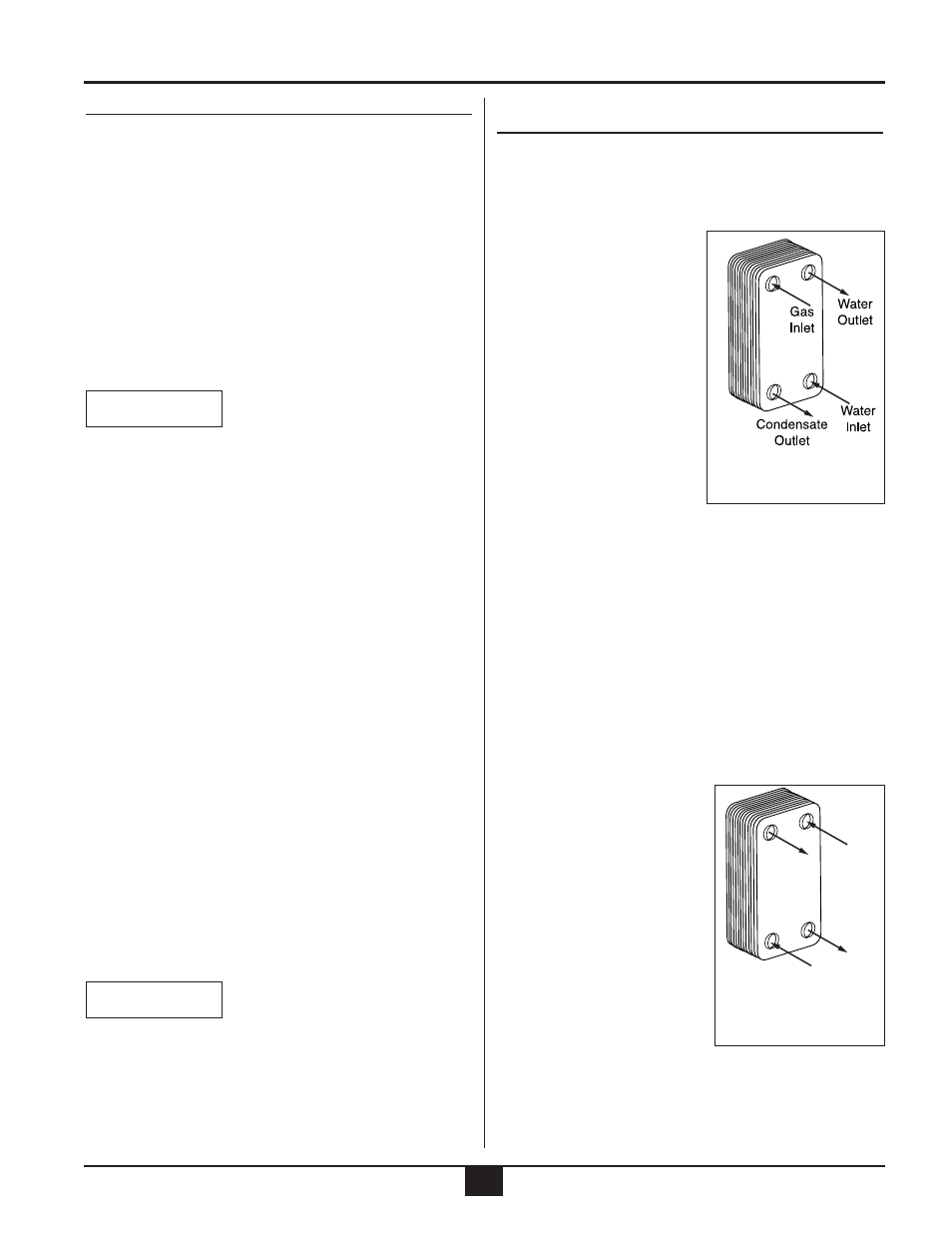
Condenser applications
•
The heat exchanger must be mounted in a vertical
position to allow gravity drainage of the condensate.
•
The refrigerant gas
must enter the heat
exchanger on the left
side (as indicated by the
color label) using the
upper connection.
•
The cooling water must
enter the lower right con-
nection of the heat
exchanger and exit from
the upper right connec-
tion. This will maintain
the counter flow concept.
Evaporator applications
•
The heat exchanger must be mounted in a vertical
position.
•
The refrigerant gas/liquid mixture must enter the
heat exchanger on the left side (as indicated by the
colored label) using the lower connection.
•
The water must enter the upper right connection of
the heat exchanger and exit from the lower right con-
nection. This will maintain the counter flow concept.
•
The thermal expansion valve should be placed close
to the inlet connection of the heat ex- changer. The
thermal expansion val- ve
sensing bulb should be
placed on the refrigerant
outlet pipe approximately
12 to 24 inches from the
heat exchanger.
•
A pressure differential
switch or flow switch
must be installed to pre-
vent possible freeze-up
due to loss of water flow.
Water
Inlet
Water
Outlet
Gas
Outlet
Gas/Liquid
Inlet
fig.13: Condenser
applications
fig.14: Evaporator
applications