Rear, P-924mk2 – Toa P-924MK2 User Manual
Page 7
7
HOT
ON
LOW
CUT
INPUT
LEVEL
OFF
0dB
– 20dB
COM
INPUT
DIRECT
4Ω
8Ω
70V
25V
COM
CLASS 2 WIRING
MAY BE USED.
INPUT
ON
OFF
0dBV
HOT
COM
–20dBV
LOW CUT
INPUT LEVEL
70V
25V
8Ω
COM
OT IN
4Ω
8
9
10
11
12
13
14
15
14
15
8
9
10
11
12
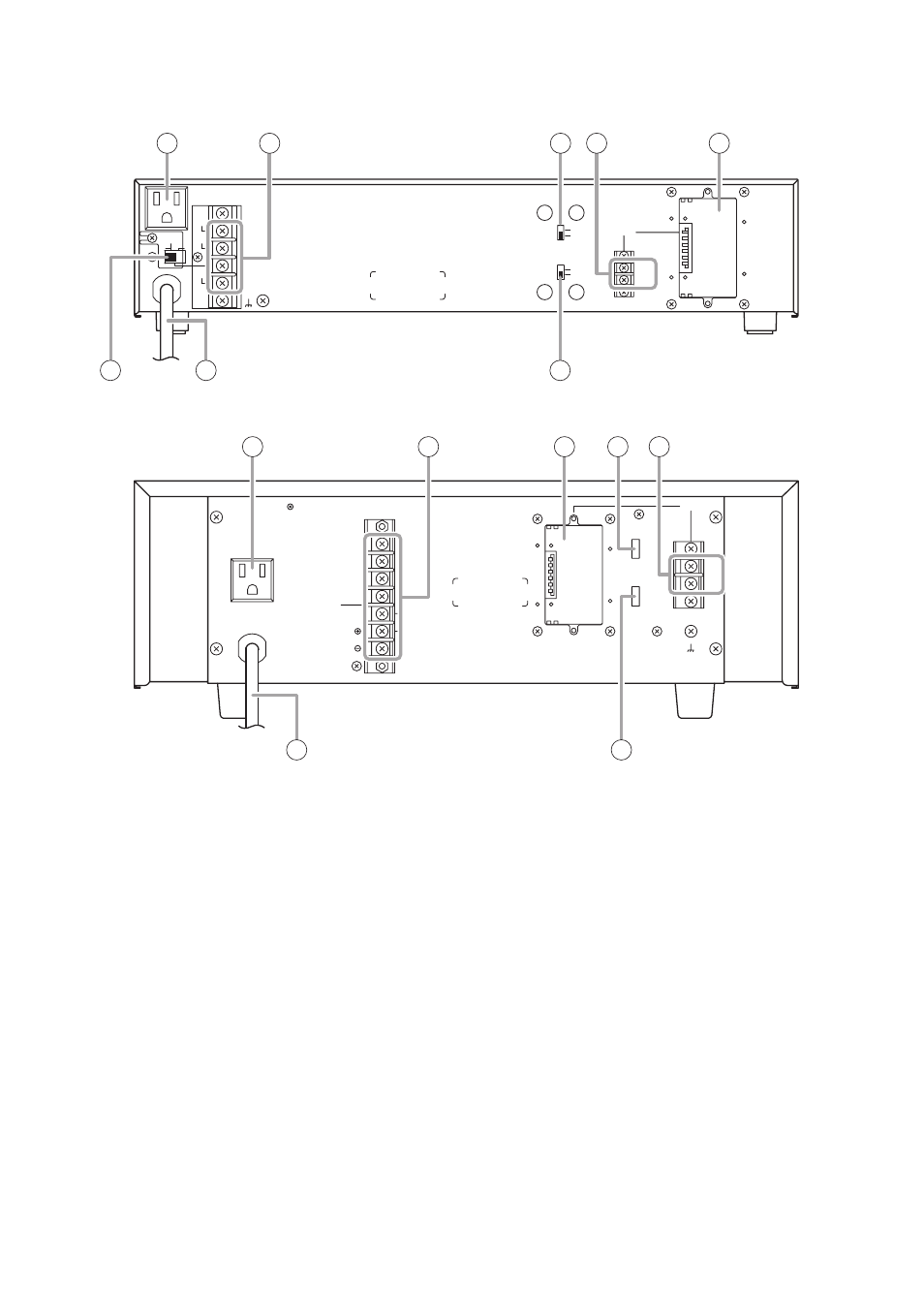
• P-906MK2, P-912MK2
This figure represents the P-906MK2.
• P-924MK2
[Rear]
8. AC outlet (Unswitched)
Provides AC power to auxiliary equipment with
power consumption of less than 500 W.
9. Speaker output terminals
Connect speaker cables to these terminals.
10. Low-cut switch [LOW CUT ON/OFF]
Set this switch to the ON position to cut off
unnecessary low frequencies.
11. Direct input terminal [INPUT]
0 dBV (1 V) or –20 dBV (100 mV) switchable, 10
kΩ, unbalanced.
Connect the line output of the external
equipment directly to this terminal.
The Direct input terminal cannot be used
simultaneously with the Module input port.
12. Module input port
Accepts one of 900 series plug-in modules. For
the selection of the most appropriate module,
refer to Plug-in Module Instruction manual.
13. Impedance selector switch [DIRECT]
(P-906MK2, P-912MK2 only)
Placing the switch in the "8 Ω" position enables
transformer-balanced 25 V, 70 V, or low-
impedance (8 Ω) speaker connection. Placing it
in the "DIRECT 4 Ω" position enables only
unbalanced low-impedance speaker connection.
For the use of this switch, refer to p. 9, "Speaker
Connections."
14. AC power cord
Connect this cord to an AC wall outlet.
15. Input level switch [INPUT LEVEL]
Select the appropriate input level "0 dBV" (1 V)
or "–20 dBV" (100 mV) depending on the module
to be used or equipment to be connected to the
Direct input terminal (11).
Normally place the switch in the " 0 dBV" position
when using the unit as an incremental power
amplifier.