Control module – Crimestopper Security Products RS-00 User Manual
Page 24
24
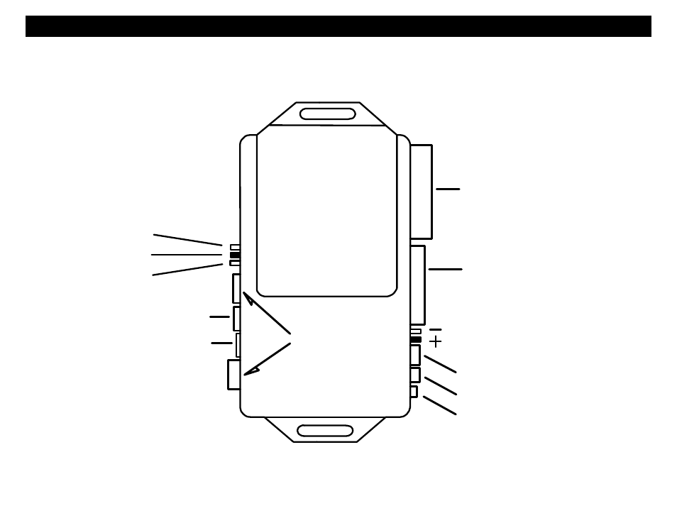
JUMPER PIN DIAGRAMS
Jumper pins are used to change/configure the operation of the on board multi-function output PINK WHITE wire and the Parking
Light WHITE wire. See the diagrams below for Jumper Pin configurations.
JUMPER PINS
Parking Lights
JUMPER PINS
Start 2
IGN 2
ACC 2
Control
Module
High Current Plug
Low Current Plug
Antenna Plug
Data Port Plug
Program Plug
Not Used
LED Plug
Door Lock Plug