Installation for infrared burner systems, Valve body assembly – Sure Heat CVS303 Natural Gas Conversion Kit User Manual
Page 5
INSTALLATION fOr
INfrArED bUrNEr SYSTEMS
Valve Body Assembly
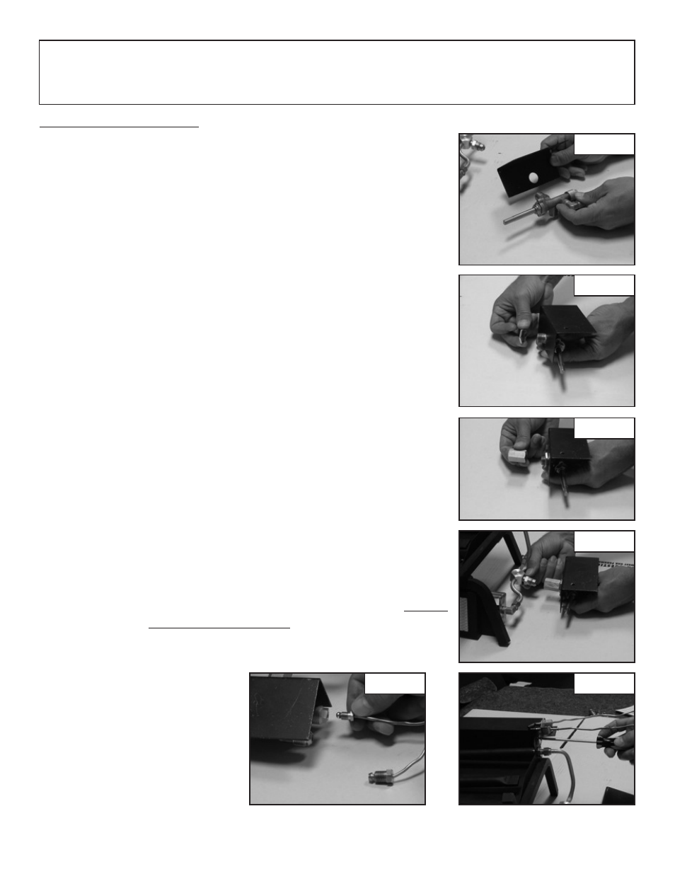
1. Slide the hole in the heat shield over the 3/8” NPT threads on the
Gas Control valve (Part # 3). (See Figure 17)
2. Then secure the heat shield in place with the lock nut (Part # 16).
(See Figure 18)
3.. Attach the 3/8” Flare to 3/8” NPT Connector (Part # 21) to the
Gas Control Valve. (See Figure 19)
NOTE: This connector fitting has two (2) different thread patterns
and will only install one way.
4. Attach the other end of the connector to the inlet fitting on the infrared
burner system. (See Figure 20)
5. Attach the pilot bracket (Part # 8) to the burner pan using the sheet
metal screw (Part # 9). (See Figure 21)
NOTE: The Pilot Bracket utilizes four mounting holes for adjustment
of the Pilot Burner Assembly should your installation require repositioning.
Repositioning of the Pilot Burner Assembly may be necessary if the log
set is experiencing intermittent shutdown. Shutdown is caused by
overheating of the Pilot Burner Assembly by the main burner flame.
If shut down is occurring, move the Pilot Burner Assembly over to the
next mounting hole so that only the tips of the Pilot Burner Assembly
are hanging over the Burner Pan.
6. Carefully bend the Thermocouple lead (Part #5) and attach to the
back of the control valve. (See Figure 22)
NOTE: When screwing into the Control Valve, hand tighten both the
Pilot Gas supply line and Thermocouple Lead, then tighten 1/8 turn
with a wrench. DO NOT OVER TIGHTEN as this will cause the Pilot
to not function properly.
Figure 17
Figure 18
Figure 19
Figure 20
Figure 21
Figure 22