Installation of natural gas pilot valve (cont.) – Sure Heat CVS303 Natural Gas Conversion Kit User Manual
Page 3
INSTALLATION OF NATURAL GAS PILOT VALVE (cont.)
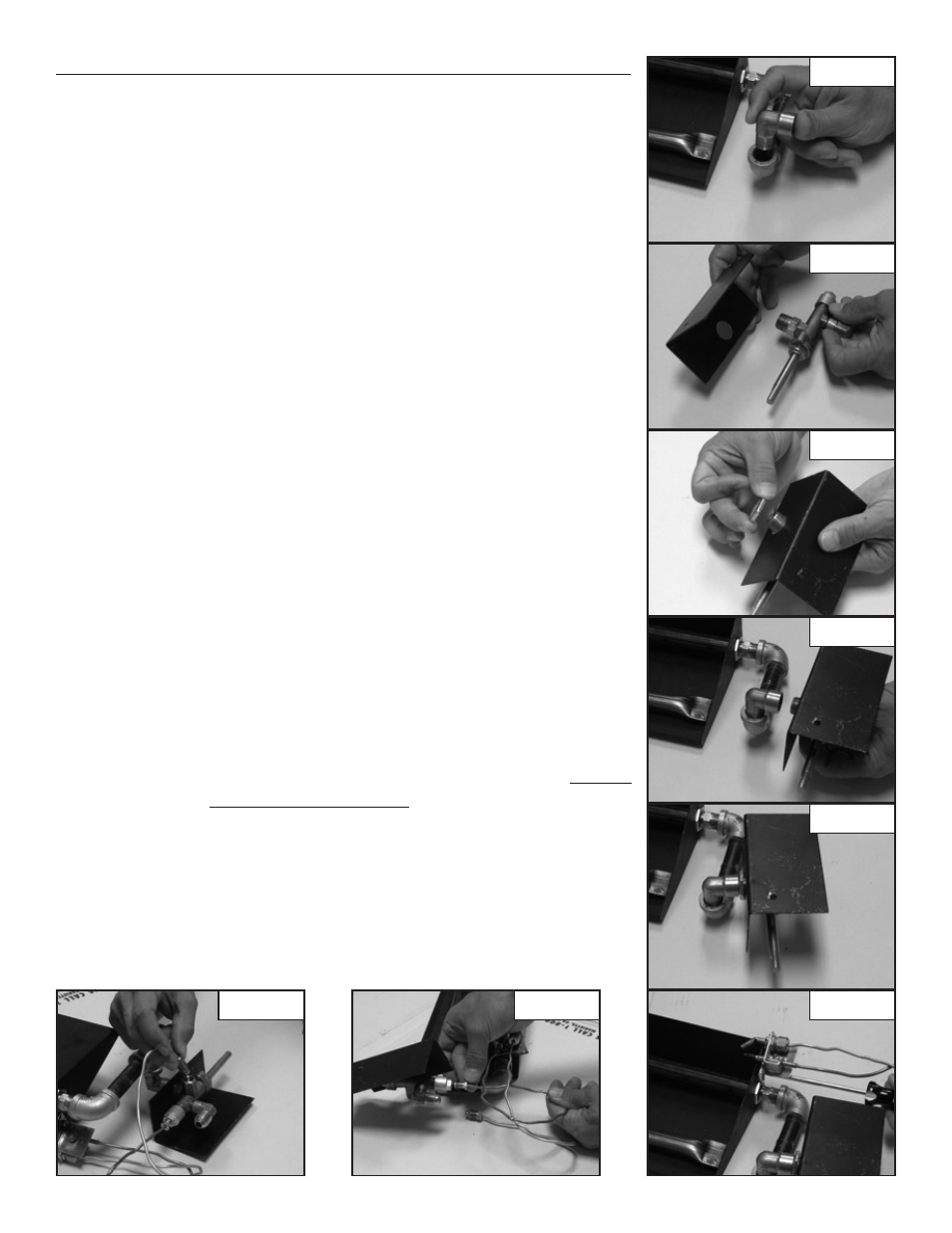
F. Connect the 90 degree street elbow (Part #17) to the 3/8” female elbow.
(See Figure 6)
G. Slide the hole in the heat shield (Part #15) over the 3/8” NPT threads on
the Gas Control Valve (Part # 3). (See Figure 7)
H. Then secure the heat shield in place with the lock nut (Part # 16).
(See Figure 8)
I. Attach the control valve & heat shield assembly to the 90 degree street
Elbow. (See Figures 9 & 10)
J. Attach the pilot bracket (Part # 8) to the burner pan using the sheet
metal screw (Part # 9). (See Figure 11)
NOTE: The Pilot Bracket utilizes four mounting holes for adjustment
of the Pilot Burner Assembly should your installation require repositioning.
Repositioning of the Pilot Burner Assembly may be necessary if the log
set is experiencing intermittent shutdown. Shutdown is caused by
overheating of the Pilot Burner Assembly by the main burner flame.
If shut down is occurring, move the Pilot Burner Assembly over to the
next mounting hole so that only the tips of the Pilot Burner Assembly
are hanging over the Burner Pan.
K. Carefully bend the Thermocouple lead (Part #5) and attach to the
back of the control valve. (See Figure 12)
NOTE: When screwing into the Control Valve, hand tighten both the
Pilot Gas supply line and Thermocouple Lead, then tighten 1/8 turn
with a wrench. DO NOT OVER TIGHTEN as this will cause the Pilot
to not function properly.
L. Attach pilot gas supply line (Part # 6) to the bottom of the gas control
valve. Care should be taken not to kink the tubing which would restrict
gas flow to the Pilot Burner. (See Figure 13)
Figure 6
Figure 7
Figure 8
Figure 9
Figure 10
Figure 12
Figure 13
Figure 11