Installation, Hardware installation – StarTech.com ST121EXT User Manual
Page 7
Instruction Manual
4
Installation
NOTE: To prevent potential electrical damage to the units in some environments, ensure
that the chassis is properly grounded.
Hardware Installation
The following instructions detail how ST1214T, ST1218T, ST121R and ST121EXT units
can be used to extend a VGA signal to remote displays, using a variety of different
configurations.
ST1214T/ ST1218T (local) and ST121R (remote)
1. Using the Transmitter Unit, you can split the VGA signal from the source into 4/8
separate VGA signals, for reception at remote locations (up to 150m (492ft) away).
2. Situate the Transmitter so that it is near your VGA video source as well as an available
power source.
3. Connect the VGA video source to the VGA IN port on the Transmitter, using a male-
female VGA cable.
4. Connect the Transmitter to the power source, using the power adapter provided.
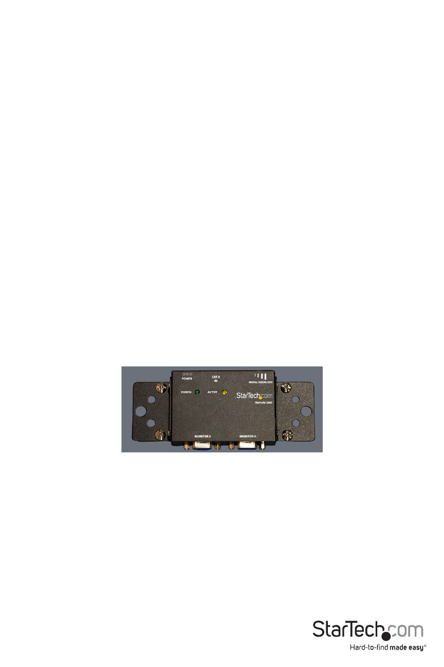
5. Situate the Receiver Unit so that it is near the intended remote display(s) and an
available power source.
OPTIONAL: with the optional mounting brackets (StarTech.com ID: ST121MOUNT), any
ST121 series receiver can be securely mounted to a wall or other surface.
6. Using the Monitor Out ports, connect the Receiver to the display. Note that each
Receiver unit can be connected to two separate displays simultaneously. To connect
two monitors, simply connect a VGA cable from the second Monitor Out to a second
display.
7. Connect the Receiver to the power source using the power adapter provided.
8. Once the Transmitter and Receiver unit(s) have been positioned, connect the Cat5
OUT ports provided by the Transmitter unit to each Receiver Unit, using standard UTP
cable, with RJ45 connectors on each end.