Parameters units nominal voltages – Specialty Concepts SCS/90 User Manual
Page 2
S
P E C I F I C A T I O N S
NOMINAL
MODEL
VOLTAGE
OPTIONS
SCS/50
12
H - Generator Start
SCS/90
24
W - Positive Ground Load
36
3R - Outdoor enclosure -
48
moderate protection
4X - Outdoor enclosure -
maximum protection
Specifications and product availability subject to change without notice.
PART NUMBERING KEY
EXAMPLE:
Model / Charge Current
Nominal Voltage
Options
SCS/50 - 12 - 4X
PARAMETERS
UNITS
NOMINAL VOLTAGES
12 v
24 v
36 v
48 v
Charge Current, Continuous
(Amps)
50
50
50
50
Charge Current, Max. (60 seconds)
(Amps)
65
65
65
65
Load Current, Continuous (1)
(Amps)
30
20
15
15
Load Current, Max. (60 seconds) (2)
(Amps)
39
26
20
20
Array Voltage, Max. Voc
(Volts)
22
44
66
88
Operating Voltage @ Battery, Min.
(Volts)
8.5
17.0
25.5
34.0
Quiescent Current (3)
(Milliamps)
40
40
40
40
Current Consumption, Charging, SCS/50 (4) (Amps)
.5
.3
.25
.2
Current Consumption, Charging, SCS/90 (4) (Amps)
1
.5
.4
.25
Current Consumption, Load Disconnected (5) (Amps)
1
1
1
1
Voltage Drop, Max. (Array to Battery),SCS/50 (Volts @ Max. rating)
.4
.4
.4
.4
Voltage Drop, Max. (Array to Battery),SCS/90 (Volts @ Max. rating)
.8
.8
.8
.8
Voltage Drop, Max. (Battery to Load)
(Volts @ Max. rating)
.1
.1
.1
.1
Full Charge Termination (6)
(Volts)
14.8 + .2
29.6 + .4
44.4 + .6
59.2 + .8
Full Charge Resumption
(Volts)
12.8 + .2
25.6 + .4
38.4 + .6
51.2 + .8
Load Disconnect (7)
(Volts)
11.5 + . 2
23.0 + .4
34.5 + .6
46.0 + .8
Load Disconnect Adjustment Range
(Volts)
11.0 to 12.0
22.0 to 24.0
33.0 to 36.0
44.0 to 48.0
Load Reconnect
(Volts)
13.0 + .3
26.0 + .6
39.0 + .9
52.0 + 1.2
Float Voltage
(Volts)
14.1 + .2
28.2 + .4
NA
NA
Float Current, Max.
(Amps)
3
1
NA
NA
Low Alarm Set-point (factory set)
(Volts)
11.8 + .1
23.6 + .2
35.4 + .3
47.2 + .4
High Alarm Set-point (factory set)
(Volts)
15.5 + .1
31.0 + .2
46.5 + .3
62.0 + .4
Alarm Relay Contact Current, Max.
(Amps)
3
3
3
3
Meter Accuracy, Voltage
1 %
1 %
1 %
1 %
Meter Accuracy, Current
1 %
1 %
1 %
1 %
Temp. Compensation coef.(from 25
°
C)
(Volts/
°
C)
-.03
-.06
-.09
-.12
Operating Temp. Range, Control circuit
(
°
C)
-20 to 50
-20 to 50
-20 to 50
-20 to 50
Operating Temp. Range, Metering
(
°
C)
0 to 50
0 to 50
0 to 50
0 to 50
Storage Temp. Range
(
°
C)
-20 to 70
-20 to 70
-20 to 70
-20 to 70
Notes:
(1) Non-inductive.
(2) Carry only, Non-switching
(3) Both relays unenergized, red LEDs off, typical value.
(4) Charge relay energized, red L.E.D. on, typical value.
(5) LVD relay energized, red L.E.D. on, typical value.
(6) Set-point adjustable. Refer to table.
(7) Decreases by 10 mv for every amp of load current
Controller SWITCH POSITIONS
Voltage
A
B
C
D
12
15.3
14.8
14.3
13.8
24
30.6
29.6
28.6
27.6
36
45.9
44.4
42.9
41.4
48
61.2
59.2
57.2
55.2
FULL CHARGE TERMINATION SET-POINTS
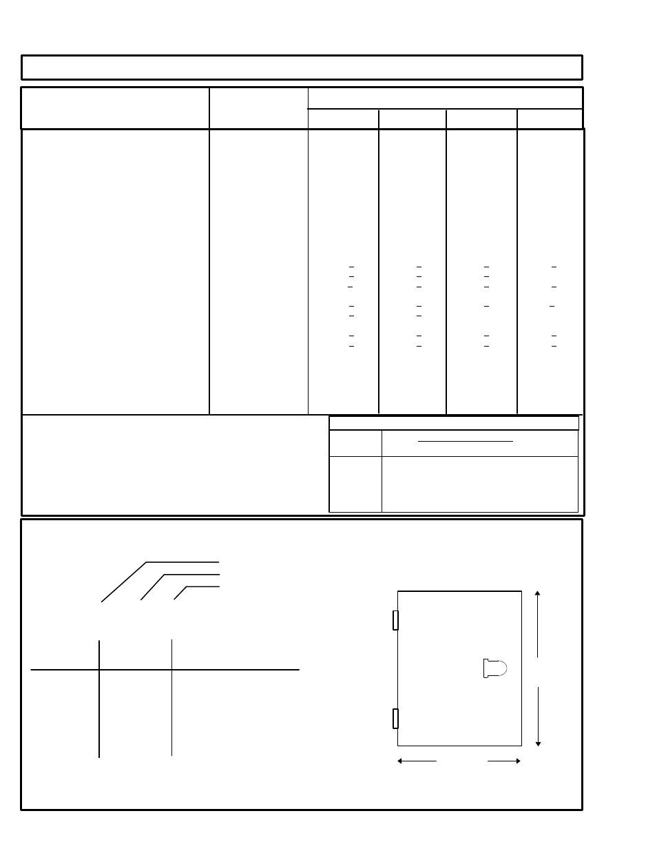
DIMENSIONS (SCS/50)
In Inches (cm)
STANDARD ENCLOSURE (NEMA 1)
15.5
( 39.4 )
13.4 ( 34.0 )
Depth: 6.0 Inch ( 15.2 cm)
Shipping weight: 30 lb. (13.5 Kgs.)