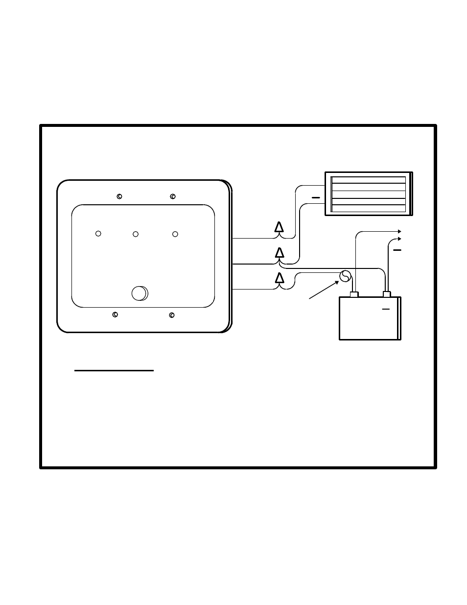
Figure 1 : wiring diagram, Sc3/10 – Specialty Concepts SC3/10) User Manual
Page 5
14. OPERATION: - Operation of the SC3/10 is now fully automatic. The SC3/10 will now
regulate the charging of batteries during conditions of heavy usage, or when left unattended
for long periods of time. If the battery voltage is below the Full Charge Termination set-point
(14.3 volts) and power is available from the array, the SC3/10 should start up in the charge
mode.
NOTE: During operation, it is normal for the SC3/10 to get warm (but not too hot to touch).
SC3/10
PANEL
BATTERY
++
+
Black (-)
Yellow (+)
Red (+)
++
To
Loads
10 Amp fuse
Figure 1 : Wiring diagram
for the
SC3/10
Wire color code
Yellow:
Panel (
+
)
Black:
Panel (
−
) / Battery (
−
)
Red:
Battery (
+
)
1. Make sure wire nuts are on tight
2. Wires from battery(s) should be less than 15 feet in length.
3. Connect loads directly to the battery and NOT the SC3/10