SmarTek Systems SAS-1 Installation at the Traffic Monitoring Site User Manual
Page 7
SmarTek Systems (www.smarteksys.com)
7
home run cable. Do not let the black wires untwist from the corresponding colored wire of
the pair. Terminate each conductor and the shield wire in each home run cable using the blue
pluggable terminal block connector (Figure 5). Once the terminal block connectors are complete,
plug them into the appropriate header on the SAS-JB circuit board as shown in Figure 5. Be sure
some of each home run cable sheathing enters the SAS-JB and tighten the strain relief to secure
the long home run cable entry into the SAS-JB.
Also check to be sure that the bare shield
wire does not short to other cable wires or components in the SAS-JB.
Note: Wireless SAS-1 installations may use a SAS Junction Box to connect a longer home run
cable to the cabinet providing power to the SAS-1 and its radio module. Since the home run
cable in this case only provides power (VDC, ground, and shield), connect only pins 5, 6, and 7
for the “Two Sensor Junction” Card or pins 10, 11, and 12 for the “One Sensor Junction” Card.
Replace the SAS-JB cover and secure the screws. Be sure the SAS-JB cover is seated to ensure a
weather tight seal (place a bead of silicone sealant around the lid before securing). Route the
long home run cable to the roadside cabinet. For longer runs, use at least 22 gauge cable.
Connecting the SAS-Cabinet Termination (SAS-CT) for an RS-422 Home Run
Identify a convenient mounting position
on the inside wall of the roadside
cabinet and mount the SAS-Cabinet
Termination (SAS-CT). If the Type 170
compatible SAS-CT is used, it slides
into the type 170 card file. Connect a
heavy ground wire from the SAS-CT to
an appropriate point to create a good
path to earth ground. Route the long
home run cable into the roadside
cabinet through conduit or a strain
relief. Inside the cabinet, route the
cable to the SAS-CT mounting
position. Remove 3 to 4 inches of the
sheathing from the cable. Be careful to
not damage the shield wire or the
insulation on each of the twisted pairs.
Do not let the black wires untwist
from the corresponding colored wire
of the pair. Terminate each conductor
and the shield wire in the long home
run cable using the blue pluggable
terminal block connector (Figure 6 or 7).
Once the pluggable terminal block
connector is complete for the long home run cable, plug it into the header on the SAS-CT circuit
board as shown in Figure 6 or 7. Tie the home run cable to the top right stand off of the SAS-CT
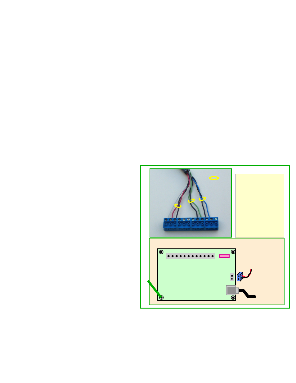
Figure 6 Connecting the SAS Cabinet Termination Rev 1.
1
12
HR
Cable
Twisted Pair
1 - Gnd (NC)
2 -
TxD+ (Blue)
3 - TxD- (Blk of Blue)
4 -
RxD+ (Green)
5 - RxD- (Blk of Grn)
6 - RTS (NC)
7 - CTS (NC)
8 - Aux+ (NC)
9 - Aux- (NC)
10 - Gnd (Blk of Red)
11 -
PWR (Red)
12 - Gnd (Shield)
To PC
Terminal Block Connector
1
SAS Cabinet Termination
(SAS-CT)
(8 - 24 VDC)
+
RJ-45
-
12
To Cabinet
Controller
Fuse
Ground