SmarTek Systems SAS-1 Installation at the Traffic Monitoring Site User Manual
Page 4
SmarTek Systems (www.smarteksys.com)
4
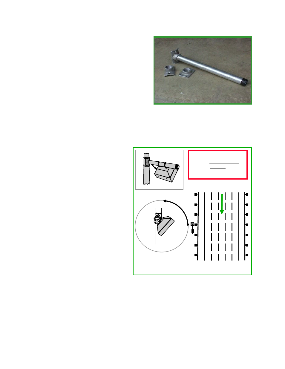
To mount the SAS-1 on the highway structure, first
attach the flange and tube assembly to the structure
so that the mounting tube is approximately parallel
to the flow of traffic. Secure the assembly using
stainless steel strapping. Position the flange and
tube assembly on the down road side of the highway
structure if possible (Figure 3). This positioning is
highly effective in keeping the SAS-1 out of sight of
motorists and therefore, reduces the chance for
vandalism.
Once the flange and tube assembly is secure, slide
the SAS-1 unit over the aluminum tube so that
the SAS-1 home run cable strain relief is toward
the uproad direction. Orienting the SAS-1 this way keeps the SAS Monitor and Setup TAI
display interpretation consistent. That is, left on the TAI display is left of the SAS-1 and right on
the TAI display is right of the SAS-1.
Rotate the SAS-1 about the tube until the
face of the sensor is toward the center of
the lanes that will be monitored as shown
in Figure 3. Remember that SAS-1
pointing does not have to be precise.
For the highway example shown in
Figure 3, the face of the SAS-1 should be
pointed toward Lane 3 or Lane 4. Once
the SAS-1 is rotated to the desired
direction, tighten the stainless steel straps
around the 2 inch mounting tube and
secure the short home run cable with tie
straps to the mounting tube and the
highway structure.
When mounting the SAS-1 on a bridge
or overpass use a mounting arrangement
that points the SAS-1 slightly away from
the sign bridge (Figure 4). This
eliminates sound reflections from
under the structure which can cause
false detections and result in poor
performance. For example, if the SAS-1 mounting position is on the downroad side of an sign
bridge, tilt the SAS-1 mounting tube upward approximately 10 to 15 degrees. This makes the
SAS-1 pointing direction further downroad and moves the SAS-1 detection zones further
downroad and away from the structure (Figure 4).
Figure 2 Mounting Tube and Flange
Figure 3 Mounting and Pointing for Multi-Lane
Rotate To Point Face
Toward Center Lanes Then
Tighten Bands
Mount on Structure
Mounting Tube Needs
To Be Approximately
Parallel
To Flow of Traffic.
Direction of Traffic
L1 L2 L3 L4 L5