SmarTek Systems SAS-1 Installation at the Traffic Monitoring Site User Manual
Page 6
SmarTek Systems (www.smarteksys.com)
6
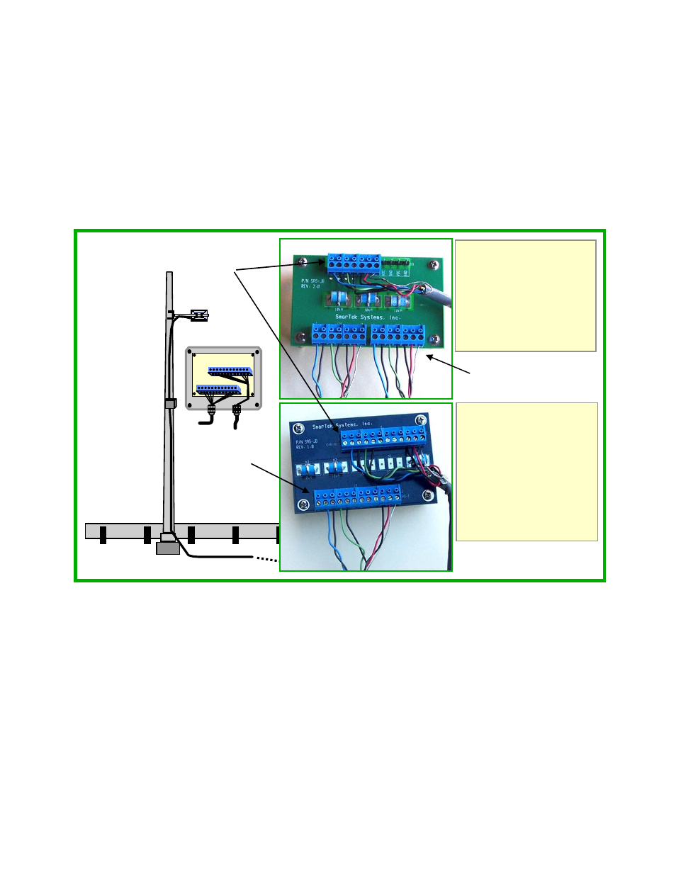
The SAS-Junction Box (SAS-JB) is used to connect the short home run cable for one or more
SAS-1 units to a single long home run cable for long runs to a roadside cabinet (Figure 5). For
shorter cable runs to the roadside cabinet (less than 50 ft), the SAS-JB may not be needed.
Route and secure the short home run cable from each SAS-1 unit along the highway structure to
a position selected for mounting the SAS-Junction Box (SAS-JB). Enough cable (short home
run) is shipped with the SAS-1 to allow the SAS-JB to be positioned (Figure 5) so that it is easy
to reach for maintenance or service without requiring a shoulder closing or a bucket truck.
Mount the SAS-JB on the highway structure using stainless steel bands. If the highway structure
used for mounting SAS-1 and the SAS-JB is wood or some other non-conducting material or if
the path to earth ground is questionable, then a grounding cable should be installed and
connected to the stainless steel mounting saddle on the SAS-JB.
Once the SAS-JB has been mounted, remove the cover and route each cable into the SAS-JB
through each strain relief as shown in Figure 5. Remove 3 or 4 inches of the sheathing from each
home run cable being careful to not damage the shield wire or the insulation on the twisted pairs.
Be sure to keep each twisted pair together since there are multiple black conductors. If
more than one SAS-1 units are to be connected to the same long home run cable, they will be
connected inside the SAS-JB using the “Two Sensor Junction “ Card instead of the “One
Sensor Junction” Card. Strip approximately 1/4 inch of insulation from each conductor in each
Figure 5 Mounting and Connecting the SAS Junction Box
SAS-JB
Long HR Cable
to Cabinet
Short HR Cable
From SAS-1
Long HR
To
Cabinet
To Single
SAS-1
SAS-JB
1
12
1
Blue
TxD+ (In)
2 Blk of Blu TxD- (In)
3
Green
RxD+ (Out)
4 Blk of Grn RxD- (Out)
5 Blk of Red GND
6
Red
VDC
7 Shield GND
Two Sensor Junction
One Sensor Junction
1 NC
2
Blue
TxD+ (In)
3 Blk of Blu TxD- (In)
4
Green
RxD+ (Out)
5 Blk of Grn RxD- (Out)
6, 7, 8, 9 NC
10 Blk of Red GND
11
Red
VDC
12 Shield GND
To Multiple SAS-1s