Slant/Fin F Series User Manual
Page 3
3
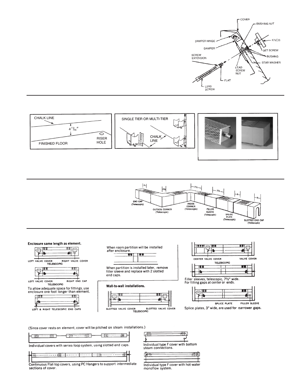
DAMPERS
DAMPER KNOB & LEAD SCREW
ASSEMBLY INSTRUCTIONS
1. Screw LEAD SCREW into LEAD SCREW NUT about 10 turns clock
wise in direction shown.
2. Line up LEAD SCREW with BUSHING hole by sliding DAMPER left or right.
3. Swing DAMPER toward COVER and guide LEAD SCREW through
BUSHING hole until beginning of SCREW thread is against BUSHING and
SCREW EXTENSION protrudes through front of COVER. Hold in place and
proceed to step 4.
4. Place KNOB on to SCREW EXTENSION and line up allen head SET
SCREW in KNOB with FLAT of SCREW EXTENSION and tighten set
screw with an allen wrench.
TYPICAL ARRANGEMENTS OF ENCLOSURES FOR SERIES J OR R
SERIES EM OR F
TYPE EM
TYPE F
SERIES EM, F AND BARE ELEMENT
STEP 1:
STEP 2:
STEP 3:
Mark chalk line.
a) Mount required hanger at chalk line.
b) Align hanger for necessary pitch.
a) Install elements, connect and test system
b) Slip on cover, insert top flange of cover
between wall and fins, cover rests on fins.
ACCESSORIES
FIT BOTH EM & F COVERS: