Slant/Fin EC-20 Installation User Manual
Page 15
EUTECTIC EC-20
15
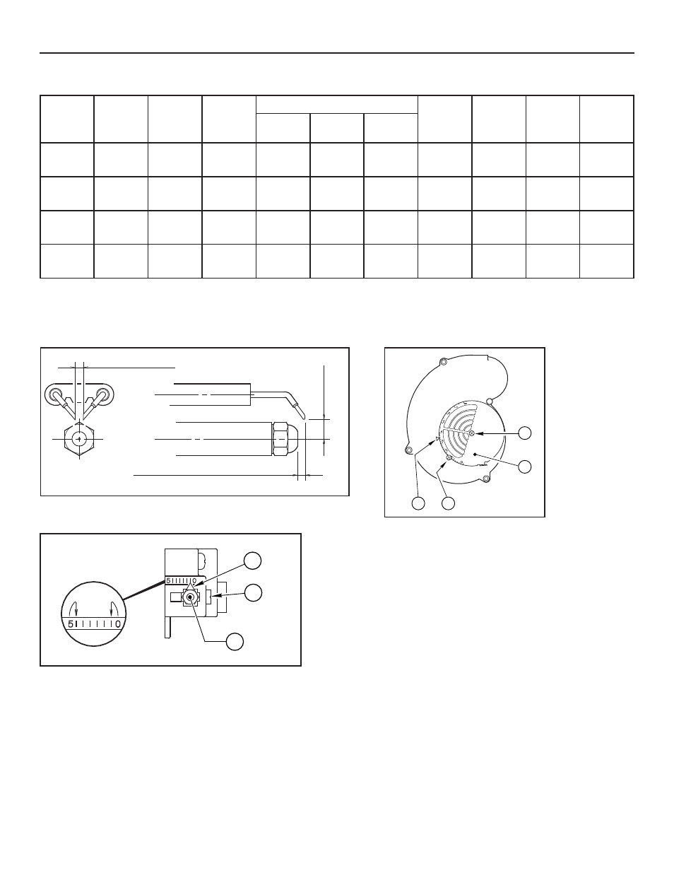
BURNER DATA - FOR RIELLO BURNERS SHIPPED WITH BOILERS ONLY
† Air shutter and head settings shown are approximate ONLY. See START-UP page 7. Seal joint between flange and air tube with a suitable high
temperature sealant, if joint was not sealed at factory.
It is suggested that due to the positive pressure observed in the chamber that the air tube hole and any other passages of the flue gas leakages
be sealed to avoid combustion gas fumes from leaking into the boiler room.
5/32” or 4 mm
13/64” or 5 mm
13
/64”
5 mm
D6003
Figure 6. Riello 40 Series. Model F-10 Electrode Setting
TURBULATOR SETTING
A) Loosen NUT (1), then turn SCREW (2) until the INDEX
MARKER (3) is aligned with the correct index number as per the
Burner Set-up chart, on page 12.
B) Retighten the RETAINING NUT (1).
NOTE: Zero and five are scale indicators only. From left to right,
the first line is 5 and the last line 0.
SETTING THE AIR ADJUSTMENT PLATE
A) Regulation of the combustion air flow is made by
adjustment of the manual AIR ADJUSTMENT PLATE
(1) after loosening the FIXING SCREWS (2 & 3).
The initial setting of the air adjustment plate should be
made according to Column 5 in the Burner Set-up Chart.
B) The proper number on the manual AIR ADJUSTMENT
PLATE (1) should line up with the SETTING INDICATOR
(4) on the fan housing cover. Once set, the air adjustment
plate should be secured in place by tightening SCREWS
2 and 3.
C) The final position of the air adjustment plate will vary on
each installation. Use instruments to establish the proper
settings for maximum CO2 and a smoke reading of zero.
NOTE
: Variations in flue gas, smoke, CO2 and temperature
readings may be experienced when the burner cover is put
in place. Therefore, the burner cover must be in place when
making the final combustion instrument readings, to ensure
proper test results.
3
2
1
D5997
Figure 7. Riello 40 Series. Model F-10 Turbulator Setting
D5231
2
1
3
4
Figure 8. Riello 40 Series. Model F-10
Setting the Air Adjustment Plate
Boiler
Model
Burner
Model
Blast
Tube
Firing
Rate
GPH
Nozzles
Oil Pump
(PSIG)
Approx.
Head
Setting †
Approx.
Air
Setting †
Burner
Insertion
Depth
Size
GPH
Angle &
Type
MFR.
EC-25
F-10
Long
1.55
1.25
60˚ B
Hago
158
1.5
2.8
7"
EC-26
F-10
Long
1.9
1.5
45˚ B
Hago
160
2.0
4.0
7"
EC-27
F-10
Long
2.25
1.75
45˚ B
Hago
165
4.0
4.5
9.5"
EC-28
F-10
Long
2.5
2.0
45˚ B
Delavan
155
5.0
4.5
9.5"