Vermont castings madison, Wall shields – Vermont Casting 1655 EN User Manual
Page 10
10
Vermont Castings Madison
Wall Shields
Wall shields should be constructed of 24 gauge or
heavier sheet metal, or another noncombustible
material such as 1/2" (13 mm) insulation board (Fig.
14) or common brick "laid on flat," with the 3
¹⁄₂
" (90
mm) side down.
Shields must be spaced out from the combustible
surface 1" (25 mm) on noncombustible spacers. The
spacers should not be directly behind the stove or
chimney connector.
Air must be able to flow between the wall and the
shield. At least 50% of the bottom 1" (25 mm) of the
shield should be open and the shield must be open at
the top.
The following examples of wall shield construction
illustrate common designs used to safely achieve
reduced clearances to combustible wall materials.
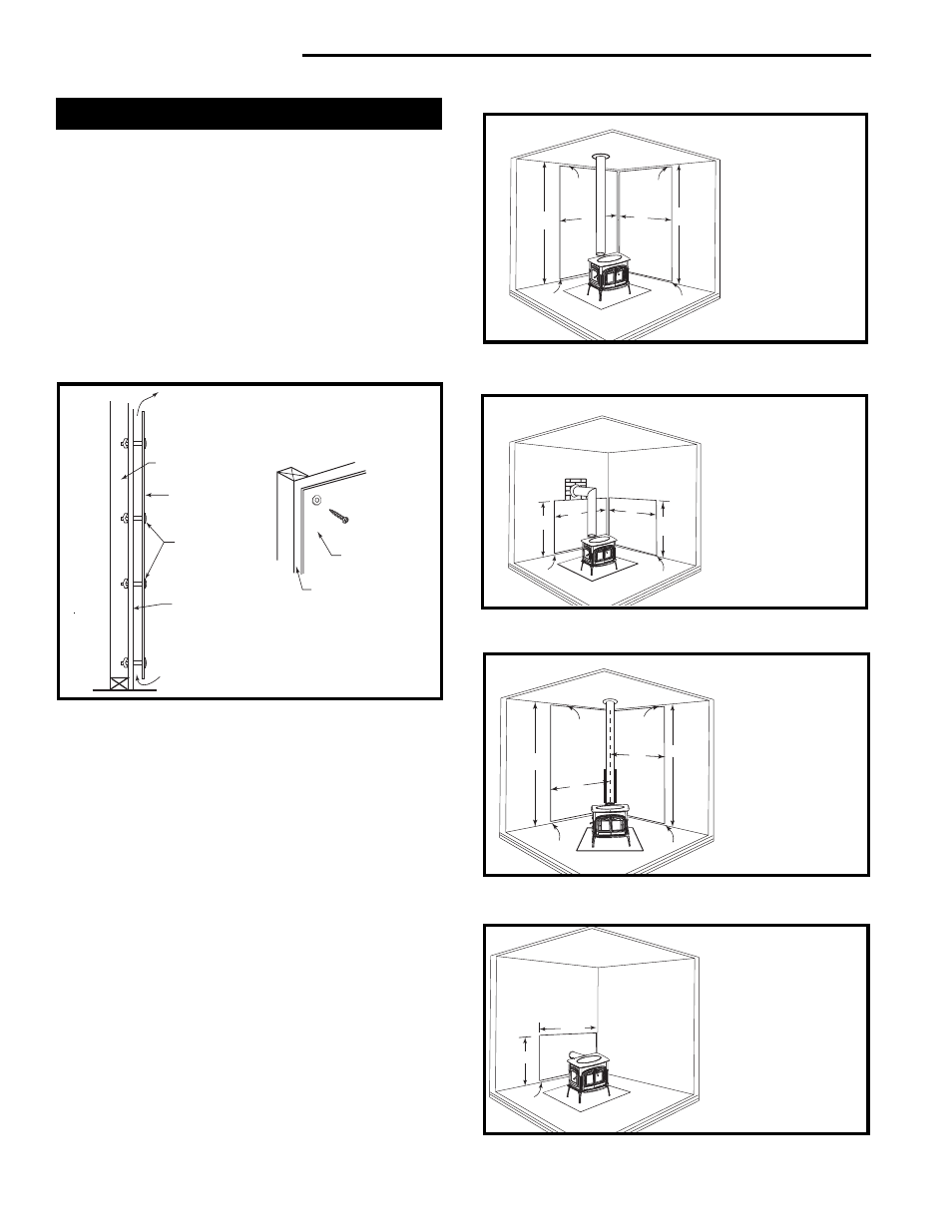
Parallel installation, vertical chimney connector,
two wall shields. Fig. 15: Reduced clearances for
both rear and side walls. Wall shields may meet at
corner if desired. Shielding for connector is centered
behind connector.
Parallel installation with rear wall pass-through,
two wall shields. Fig. 16: Reduced clearances for
both rear and side walls. Wall shields may meet at
corner if desired. Shielding for connector is centered
behind connector. Wall pass-through must comply
with codes.
Corner installation, vertical chimney connector,
two wall shields. Fig. 17: Reduced side clearances.
Wall shields MUST meet at corner.
Parallel installation with rear exit, rear wall pass-
through, rear wall shield. Fig. 18: Reduced
clearances for rear wall. Shielding for connector is
centered behind connector. Wall pass-through must
comply with codes.
Fig. 15 Parallel installation, vertical chimney connector, two
wall shields.
C
C
C
B
A
B
A
C
ST550
A = 48” (1219 mm)
B = Max. - C
C = 1” (25 mm)
Fig. 16 Parallel installation with rear wall pass-through, two
wall shields.
A
B
C
B
A
C
ST551
A = 48” (1219 mm)
B = 48” (1219 mm)
C = 1” (25 mm)
Fig. 17 Corner installation, vertical chimney connector, two
wall shields.
B
B
C
C
A
A
C
C
ST552
A = 48” (1219 mm)
B = Max. - C
C = 1” (25 mm)
C
A
B
A = 48” (1219 mm)
B = 48” (1219 mm)
C = 1” (25 mm)
ST564
Fig. 18 Parallel installation, rear wall pass through, rear wall
shield.
Fig. 14 Approved Wall shield construction
Air flow
Wall shield
Air flow
Stud wall
framing
Noncombustible
spacers and
fasteners
Drywall
Metal Spacer
Shield
ST248a