Sigtronics SAS-640 User Manual
Page 4
UPGRADING A SPA INSTALLATION TO A SAS
Chassis Mounting
The SAS-440 is specifically designed to easily replace a
SPA-400. Similarly, the SAS-640 can replace a SPA-600.
The panels are exactly the same dimensions (1” x 2.5”),
however the SAS units are 1 3/4” longer than the SPA units.
You will have to make sure that you have the extra depth
required behind your panel. The five mounting holes are
exactly in the same positions. Only the center hole will have
to be changed (enlarged from 1/4” to 1/2”).
To upgrade, first remove the SPA unit from the aircraft panel.
This is done by unscrewing the two Phillips head screws
and the nut on the ON/OFF switch. Remove the printed SPA
panel. Pull the SPA unit out and unplug the white connector
from the wiring harness. Next, drill the center hole in the
aircraft panel out to 1/2”. Then to mount the SAS chassis
(see Figure 2 on page 2):
1. Remove the knobs from the Volume and OFF/ALL/ISO
controls using a 0.050” Allen wrench. NOTE: DO NOT
REMOVE the nuts from the Volume (VOL), Squelch (SQ),
or OFF/ALL/ISO controls.
2. Insert the SAS unit from the rear of the aircraft panel
with the appropriate arrow on the unit chassis pointing
upwards.
3. Install the printed SAS panel and lightly thread the two
4-40 screws through the holes in intercom panel. The
nuts on the Volume and OFF/ALL/ISO controls should fit
inside the 3/8” diameter holes.
4. Tighten the two screws.
5. Put the knobs on the Volume and OFF/ALL/ISO control
shafts and tighten the Allen screws.
Wiring Change
The only wiring change to an existing SPA installation is to
rewire the co-pilot and passenger(s) headphone lines. You
will not need the 4 foot interface cable that comes with the
SAS system. Instead, you will use the SPA harness already
in the aircraft. Find the single white / green wire with female
pin (supplied). Push the pin into the vacant hole at pin 12
next to the white / orange wire in your existing SPA interface
harness. Make sure it is in as far as the other pins and does
not pull out. Then plug the cable on the SAS unit into the
modified SPA interface cable.
In an SPA installation, the tip terminals of the co-pilot and
passenger headphone jacks are wired to the blue wire (pin
3). They need to be disconnected from there and connected
to the white / green wire (pin 12) (see Figure 4 on page 3).
Make sure that the blue wire (pin 3) is still connected to
the tip of the pilot’s headphone jack as well as to the radio
headphone line.
INSTALLATION CHECK-OUT AND ADJUSTMENTS
After the unit is installed, again check that the SAS unit
chassis, jacks, and wiring harness are clear of all aircraft
operating controls and cause no interference with them.
Check out the SAS unit installation by following the
instructions below.
Plug in all the headset mic and phone plugs into the
respective intercom jacks. Put on the pilot’s headset and
position the boom mic close to the mouth, as is the practice
with a hand-held mic. Voice clarity is best when the mic is
at one side of the mouth and 1/4” from the lips.
To assure that the aircraft radios, pilot’s headset, and
PTT switch are connected and functioning properly, turn
the SAS units OFF/ALL/ISO switch to the “OFF” position.
If applicable, set the aircraft audio panel to “Headphone”
position. Then turn on the aircraft radio(s) as usual, and
verify that the pilot can hear the radios and can transmit
using his push-to-talk switch and headset. Aircraft radio(s)
and audio panel should operate exactly as they did before
the SAS system was installed. Aircraft radio reception should
not be heard in the co-pilot or passenger headsets. There
should be no intercom between headsets with the SAS unit
turned “OFF”.
Next turn the SAS unit OFF/ALL/ISO switch to the “ALL”
position. Set the SAS volume control to mid-position. Verify
that all headset positions can now intercom with each other,
including the passengers. Verify that both pilot and co-pilot
can operate the aircraft radio(s). In this mode all headsets
on the intercom will hear the aircraft radio(s).
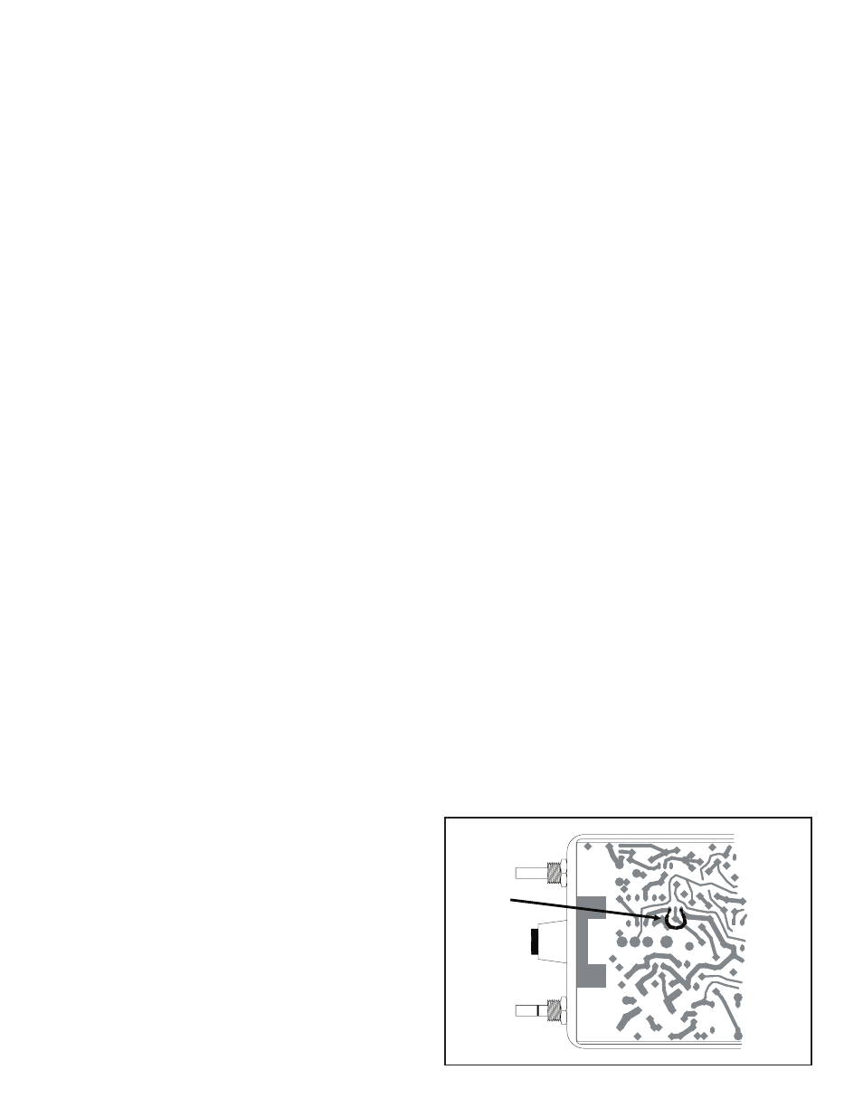
It may be necessary at this time to adjust the SAS unit
mic output to the aircraft radios. A small adjustable
potentiometer is provided inside the unit for this purpose. It
is accessible through a hole in the side of the SAS chassis.
It is marked “Mod. Adj.”, and can be adjusted with a small
blade screwdriver. In the event of over-modulation (garbled)
or reports of weak transmissions over the aircraft radio, an
appropriate adjustment can be made. Clockwise rotation
increases the output level to the aircraft radio mic input.
Counter-clockwise rotation decreases modulation level. This
adjustment sometimes needs to be made after the initial
installation of the intercom or if a new radio is installed. (The
output is set for unity gain at Sigtronics).
FIGURE 5
SIDETONE MOD.
4