Sigtronics SAS-640 User Manual
Page 3
4. Install insulating washers as necessary if the barrel of the
mic jack is mounted in metal.
For the headphone jack, just add the blue wire (pin 3) to
the tip terminal. No need to remove existing wires on the
headphone jack.
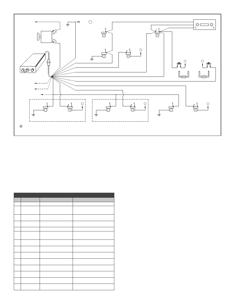
WIRING INSTRUCTIONS
Connections should be made as shown in Figure 4 and
indicated in Table 1. If longer wire lengths are required, use
a good quality hook-up wire - 22 gauge or larger. Although
not necessary, shielded audio wire can be used if desired.
This can simplify the wiring process.
*1. The blue wire from Pin 3 must be connected to the aircraft
radio headphone output - NOT the speaker output.
*2. Connect all intercom mic jack grounds to a single aircraft
chassis ground point - Point “A” - as shown in Figure
4. (Use the black washers supplied to insulate the
intercom mic jacks from aircraft chassis ground). Note
this intercom central grounding point is used to eliminate
any unwanted electrical noises, such as alternator whine
or strobe noise, from being induced into the intercom
system through the grounds. All intercom mic jack barrels
must be insulated from ground where they are mounted
and connected back to Point “A” on their own individual
ground wire. Similarly, both intercom ground wires (pin
4) and the push-to- talk switch grounds must also be
connected back to Point “A”. It is not necessary, however,
to connect the headphone jack barrels to Point “A”. They
can either be grounded where they are mounted or some
place nearby.
*3. The red wire may be connected to either 12V (14V) or
24V (28V) power source. No switching or adjustments
are required to operate from either source.
*4. Tan wires (pins 8 and 9) are only used on installations
that require extra intercom positions.
*5. Provided on SAS-640 units only.
Skip down to the INSTALLATION CHECK OUT AND
ADJUSTMENTS section on page 4.
���
���
��
���
���
���� �����������
��� ���������
��� �����������
���� ������������
��� ���
��� ����
��� �����
���� ����������
��������������� ������������ �������
������ �
�������� ������� ������
� �������� �� ������� ����� �����
�������� �����
��� �����
��������� �����
�����
����� ��� ���
��
��
��
��
��
�
�
��
��
��
�
�
���� ����
���� ����
�� ��������
����� ����
����� ���
��������
�������
�������
�� ����
������� � �������
��������
�� ����� ��
��� �����
�� ����� ��
��� �����
�� ����� �� � ��
��������� ������
��������� ����
������
���
������
���
����
��� ����
��������� �
�
��
�
��
��������� ����
������
���
������
���
����
��� ����
��������� �
�
��
����
������
���
������
��������
��������� ����
���
��������
��� ����
���������
�������
������
������
����� �
���
��������
���������
����
�����
��������� ����
������
���
������
���
����
�����
��� ����
�
��
���
����
��������
���� ���
����
����������������� ��������� ����
�����
��� ������
�
��
�
��
��������
��� ������
TABLE 1 – See Wiring Instructions
PIN
WIRE COLOR
FUNCTION
CONNECT TO
1
White / Black
Pilot Mic Input
Ring Terminal of Pilot Mic Jack
2
White / Red
Pilot and Radio Transmit
Switch Input
Pilot Transmit Switch (PTT) & Radio
Key Input (Switch to Ground to
Transmit)
3
Blue *1
Pilot Headphone - Radio &
Intercom Outputs
Radio Headphone Output and Tip
Terminal of Pilot Headphone Jack
4
Black *2
Intercom Central Grounding
Point “A”
Aircraft Chassis Ground
5
N/C
None
No Connection
6
Brown
Transmit Mic Audio Output
Ring Terminal of Aircraft Hand Mic
Jack or Mic Input of Aircraft Radio
or Audio Panel
7
Red *3
12 through 24 VDC Power
Input
Intercom Circuit Breaker
8
Tan *4
Passenger #1 Mic Input
Ring Terminal of Passenger #1
Intercom Mic Jack
9
Tan *4
Passenger #2 Mic Input
Ring Terminal of Passenger #2
Intercom Mic Jack
10 White / Blue
Co-Pilot Radio Transmit
Switch Input
Co-Pilot Transmit Switch (PTT)
(Switch to Ground to Transmit)
11
White / Orange Co-Pilot Mic Input
Ring Terminal of Co-Pilot Intercom
Mic Jack
12 White / Green
Co-Pilot & Passenger
Intercom Headphone Output
Tip Terminal of Co-Pilot &
Passenger Headphone Jacks
13 Tan *5
Passenger #3 Mic Input
Ring Terminal of Passenger #3
Intercom Mic Jack
14 Tan *5
Passenger #4 Mic Input
Ring Terminal of Passenger #4
Intercom Mic Jack
3