Sigtronics SAS-640 User Manual
Page 2
CHASSIS INSTALLATION
To upgrade an existing SPA-400 installation to a SAS-440
or a SPA-600 to SAS-640 skip to the “UPGRADING A
SPA INSTALLATION TO A SAS” section on page 3. For a
completely new intercom installation continue below.
Hardware Supplied
Besides the intercom unit and these instructions, each SAS
system comes with the following hardware:
SAS-440 SAS-640
Headphone Output Jacks - Accept standard
0.250” aircraft headphone plugs.
4
6
Microphone Input Jacks - Accept standard
0.206” aircraft microphone plugs. (U93 plug
compatible jacks can be used in place of the
jacks provided).
4
6
Mic Jack Insulating Washers, Flat
4
6
Mic Jack Insulating Washers, Shoulder
4
6
Intercom Panel - lettered on both sides.
1
1
Intercom Control Knobs
2
2
Mounting Screws 4-40 x 1/2
2
2
Drill Template - Adhesive backed hole size
pattern for drilling aircraft panel.
1
1
Aircraft / Intercom Interface Cable (4 feet long) 1
1
Single White / Green Wire with pin (4 feet long) 1
1
UNIT PLACEMENT
The SAS unit has been designed to mount either horizontally
or vertically in your aircraft panel.
The location selected for the SAS unit requires a minimum
front panel area of 2 1/2” by 1”. Depth required behind panel
is 6” plus cable access.
CAUTION: Move the aircraft flight controls through the limits
of travel while observing the selected area and making sure
that the rear of the intercom and cable will not interfere with
any aircraft control components.
PANEL PREPARATION:
1. Position the adhesive drill template on the aircraft panel
in the selected area.
2. Center punch each hole at the cross lines. (The five holes
are in a straight line and equally spaced 0.4” apart).
3. Drill 1/8” pilot holes in all five places.
4. Enlarge two holes to 3/8” and one hole to 1/2” per the
template.
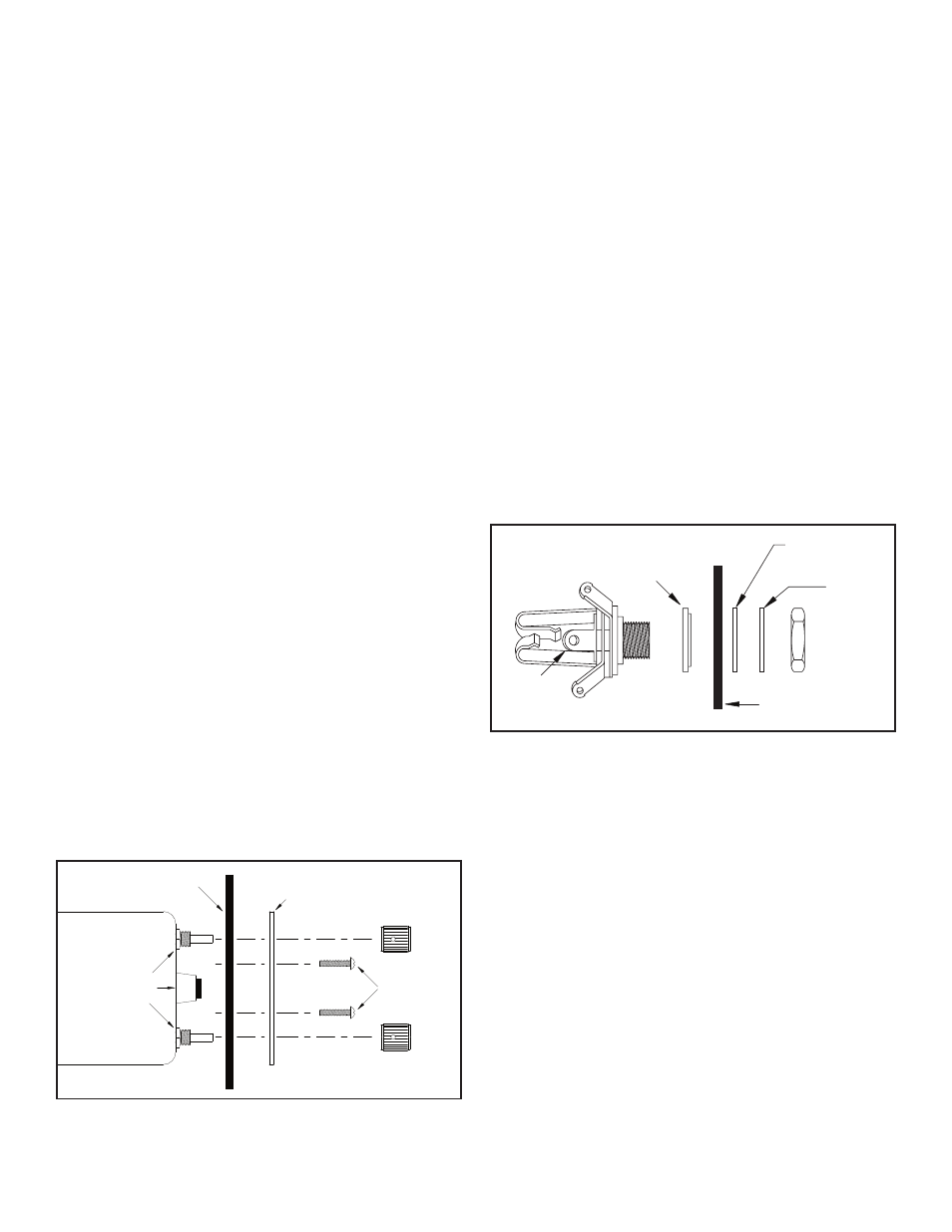
MOUNTING CHASSIS: See Figure 2
1. Remove the knobs from the Volume and OFF/ALL/ISO
controls using a 0.050” Allen wrench. NOTE: DO NOT
REMOVE the nuts from the Volume, Squelch, or OFF/
ALL/ISO controls.
2. Insert the SAS unit from the rear of the aircraft panel
with the appropriate arrow on the unit chassis pointing
upwards.
3. Install the printed SAS panel and lightly thread the two
4-40 screws through the holes in intercom panel. The
nuts on the Volume and OFF/ALL/ISO controls should fit
inside the 3/8” diameter holes.
4. Tighten the two screws.
5. Put the knobs on the Volume (VOL) and OFF/ALL/ISO
control shafts and tighten the Allen screws.
MOUNTING HEADPHONE AND MICROPHONE JACKS
(See Figure 3)
1. Locate the mounting areas. (One mic and one headphone
jack required for each headset). Again, make sure that
the jacks will not interfere with any aircraft control
components.
2. Drill 3/8” diameter holes for headphone jacks and
install.
3. Drill 1/2” diameter holes for the mic jacks and install with
the insulating washers supplied. (See Figure 3).
Note: If the aircraft already has pilot headset jacks, they
can be used for intercom, however, the mic jack must be
re-wired as follows:
1. Remove any existing wires from the tip, ring, and barrel
connections.
2. Connect the intercom White / Black wire to the ring
terminal.
3. Connect one end of a ground wire to the barrel terminal
of the mic jack and connect the other end to Point “A”.
�� ��� ������
����� ����
��������
�����
��������
�����
��������
����
���� � ��� ������
����
��������
������
����
���������
������
����
�����
������
���
��������
�����
����
������
���
FIGURE 2
FIGURE 3
MICROPHONE JACK
2