Microphone gain selection, Communications antenna installation notes, Icrophone – PS Engineering PMA5000EX Installation Manual User Manual
Page 13: Election, Ommunications, Ntenna, Nstallation, Otes
PS Engineering
PMA5000EX Audio Selector Panel and Intercom System
Installation and Operator’s Manual
200-550-0100
Page 2-7
Rev. 1 Jan. 2011
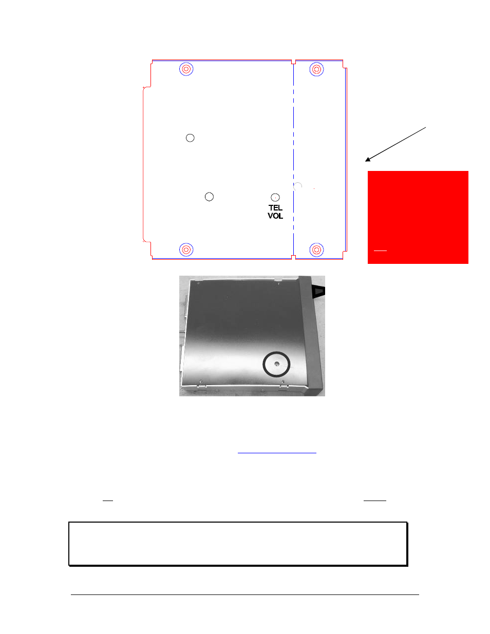
Figure 2-2- PMA5000EX Adjustments, top cover
Figure 2-3 – Unswitched 3 Audio Level (bottom cover removed)
2.6.1
Microphone Gain Selection
In very high noise environments (such as open cockpit, etc.) the PMA5000EX can be switched to a lower
microphone gain by configuring internal switches.
2.7 Communications Antenna Installation Notes
For best results while in Split Mode, it is recommended that the one VHF communications antenna is lo-
cated on top of the aircraft while the other communications antenna is installed on the bottom. Any an-
tenna relocation should be accomplished in accordance with AC 43.13-2B, and /or aircraft manufacturers’
recommendations.
WARNING
It is probable that radio interference will occur in the split mode when the frequencies of the two ai r-
craft radios are adjacent, and/or the antennas are physically close together. PS Engineering makes
no expressed or implied warranties regarding the suitability of the PMA5000EX in Split Mode.
Front
of unit
NOTE:
If top cover is removed
for ANY reason, you
MUST replace the cover
screws with the proper
length, otherwise damage
will result.
Shorter Screw