Ty91 vhf com interface, Ty91 connector (trig ty91(l) -05 only), Interfacing the ty91(l) as single, com 1 or com 2 – PS Engineering PAR200A Installation Manual User Manual
Page 11: Antenna cable
PS Engineering Inc. ®
PAR200A Audio Selector Panel, COM radio Controller and Intercom System
Installation and Operator’s Manual
200-228-0200
Page 2-4
June 2014
2.5 TY91 VHF COM Interface
2.5.1
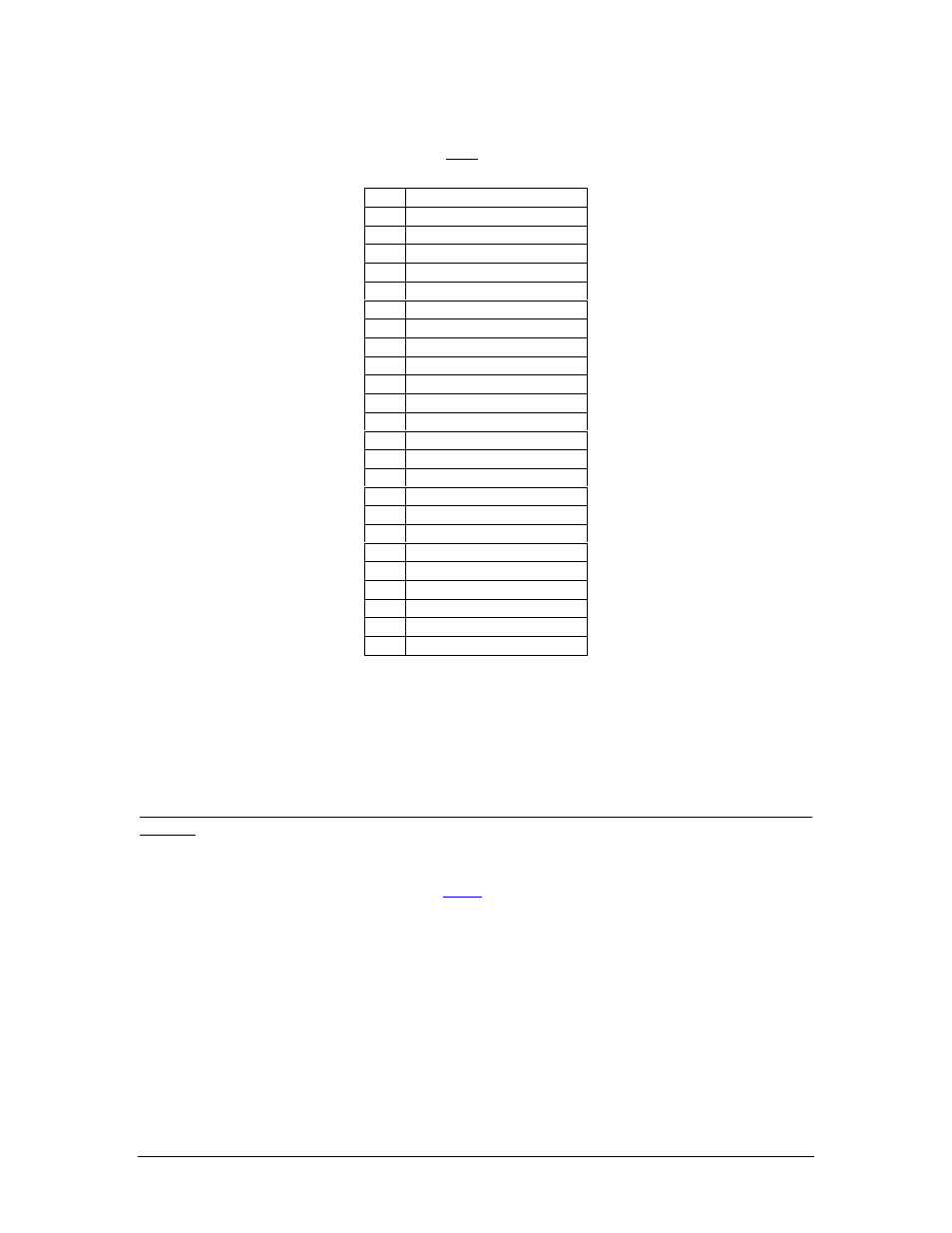
TY91 Connector (Trig TY91(L) -05 only)
The TY91 has a 25-pin crimp type connector.
1
Com Audio Low
2
COM Audio High
3
No Connect
4
No Connect
5
RS232RX (data in-TX)
6
RS232TX (data out-RX)
7
No Connect
8
No Connect
9
Aircraft Ground
10
No Connect
11
No Connect
12
Controller Radio Power
13
Radio On
14
No Connect
15
COM Mic Key
16
No Connect
17
No Connect
18
Transmit Interlock
19
Airframe Ground
20
No Connect
21
No Connect
22
Ground (Not Used)
23
COM Mic Audio Hi
24
Aircraft Power
25
Aircraft Power
2.5.2
Interfacing the TY91(L) as Single, COM 1 or COM 2
The PAR200A/ Trig TY91(L) can be configured to be a stand-alone COM, or as COM 1 or COM 2 in a
multiple radio installation. In this case, PS Engineering recommends that the PAR200A/TY91(L) be used
as COM 2. In the event of a failure, the PAR200A will be in fail-safe, and COM 1 can be used.
The PAR200A must be configured with an installation strap when PAR200A radio is being used as COM
2, by applying ground to J1, Pin 25. J1, pin 26 is a convenient ground.
NOTE: When wiring remote radio as COM 1, leave J1-25 open. When wiring as COM 2, connect J1-25
to J1-26.
If the TY91(L) is used as COM 1, the PAR200A can fail-safe to it, because it is divided internally as audio
panel and COM control. In addition, the TY91(L) power supply is provided by an independent circuit
breaker and power supply in the PAR200A. See
for operational information.
When properly selected, the PAR200A LCD display will read either COM 1 (includes stand-alone), or
COM 2.
2.5.3
Antenna Cable
Use a high quality 50 ohm coaxial cable, such as RG400 or RG142B. When routing the cable, ensure that
you:
Route the cable away from sources of heat.
Route the cable away from potential interference sources such as ignition wiring, 400Hz genera-
tors, fluorescent lighting and electric motors.
Allow a minimum separation of 300mm (12 inches) from an ADF antenna cable.
Keep the cable run as short as possible.