PS Engineering PMA7000M-S Installation Manual User Manual
Page 9
PS Engineering
PMA7000M-S Series Audio Selector Panel and Intercom System
Installation and Operator’s Manual
200-070-0012
Page 2-2
Rev. 12, Sept. 2000
NOTE: The mounting hole configuration for the PMA7000M-S is identical to the PMA6000 series and
KMA-24 Audio Selector Panels.
2.3.3 Mounting Rack Installation
Remove the unit from the mounting tray by unscrewing the 3/32" hex-head screw that is in the center of the
unit. Use caution to avoid hitting the photo-detector lens. Carefully slide the unit free of the tray. Set the
unit aside in a safe location until needed. Install the tray using six clip nuts (475-630-0002), and six FHP 6-
32 x ½" screws (475-632-0012). The audio selector panel must be supported at front and rear of the mount-
ing tray.
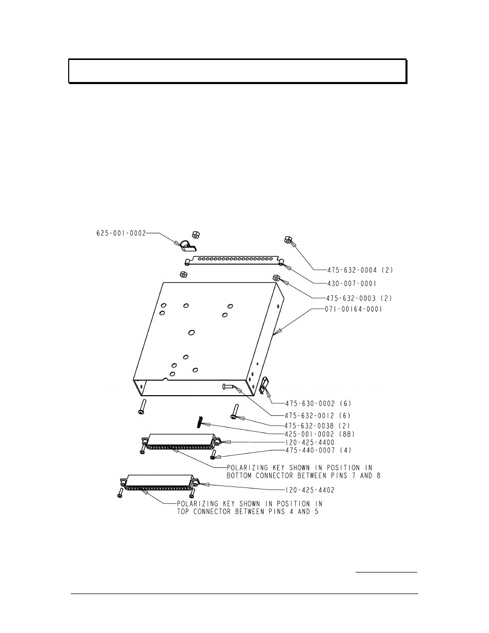
2.3.4 Tray and Connector Assembly
The unit connectors mate directly with the circuit boards in the PMA7000M-S. The connectors are a Molex
crimp-type, and require the use of a Molex hand crimp tool, EDP P/N 11-01-0203, CR6115B (or equiv.).
The connectors are mounted to the unit tray with #4-40 screws (475-440-0007), from the inside of the tray.
Ensure that proper strain relief and chafing precautions are made during wiring and installation, using the
cable clamp (625-001-0002). Secure the ground bar (430-630-0002), if desired using, #6-32 nuts (475-632-
0003) and #6-32 lock nuts (475-632-0004).
Figure 2-1 Tray Assembly Drawing
2.4 Cable Harness Wiring
Referring to the appropriate Appendix, assemble a wiring harness as required for the installation. All wires
must be MIL-SPEC in accordance with current regulations. Two- and three-conductor shielded wire must