Installation, Installing ethernet switch – PRG Ethernet Switch User Manual
Page 9
PRG SERIES 400
®
ETHERNET SWITCH USER MANUAL
7
INSTALLATION
Installing Ethernet Switch
A Series 400 Ethernet Switch can be used independently or installed directly in a Series 400 rack chassis, using any
blank space above the LED Meter Module.
To install in Series 400 rack:
Step
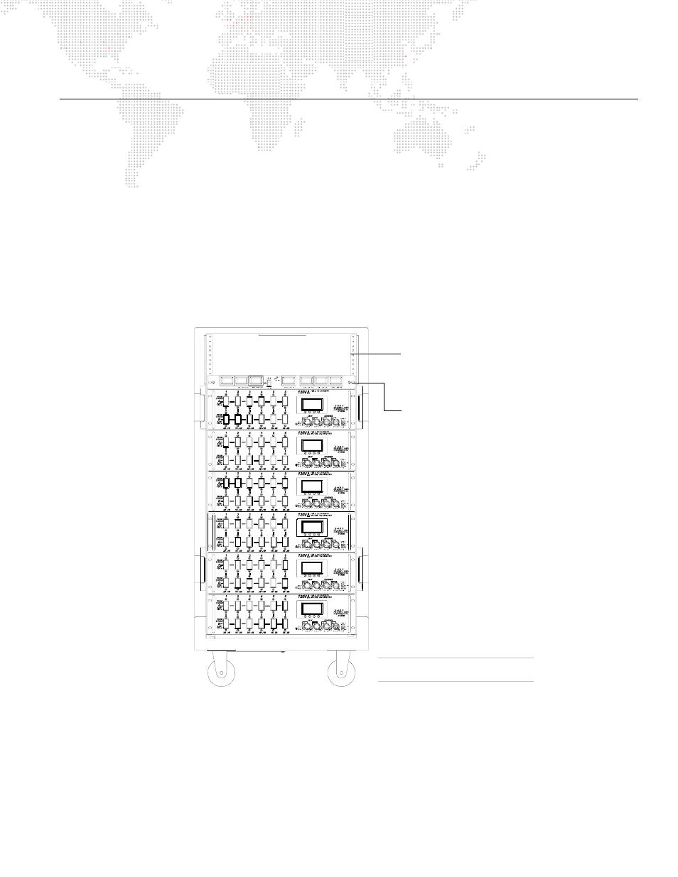
1. Install Ethernet Switch as required in top portion of rack chassis (Figure 7).
Step
2. At Ethernet Switch rear panel, connect AC Line Cord 208V PowerCon® Cable (supplied) to Neutrik®
connector.
Step
3. After power is applied, verify that ON indicator is lit.
Step
4. At front panel, connect data cables as required. Refer to
"Connecting Ethernet Switch to System"
Figure 7: Series 400 Rack
3U of rack space for
adding additional signal
processing devices.
EXAMPLE CONFIGURATION
S400 Rack Components May Vary
SERIES 400 RACK CHASSIS
LED Meter Module