Connecting ethernet switch to system, Both, Only – PRG Ethernet Switch User Manual
Page 10: Cat5e copper wire
8
PRG SERIES 400
®
ETHERNET SWITCH USER MANUAL
Connecting Ethernet Switch to System
The Series 400 10-Port Ethernet Switch connects Ethernet devices using
both
CAT5e copper wire
and
armored fiber
optic cable. Copper wire communication ports conform to 10/100Base-Tx standards and the fiber ports conform to
10/100Base-Fx standards. The Series 400 7-Port Ethernet Switch connects Ethernet devices using
only
CAT5e
copper wire.
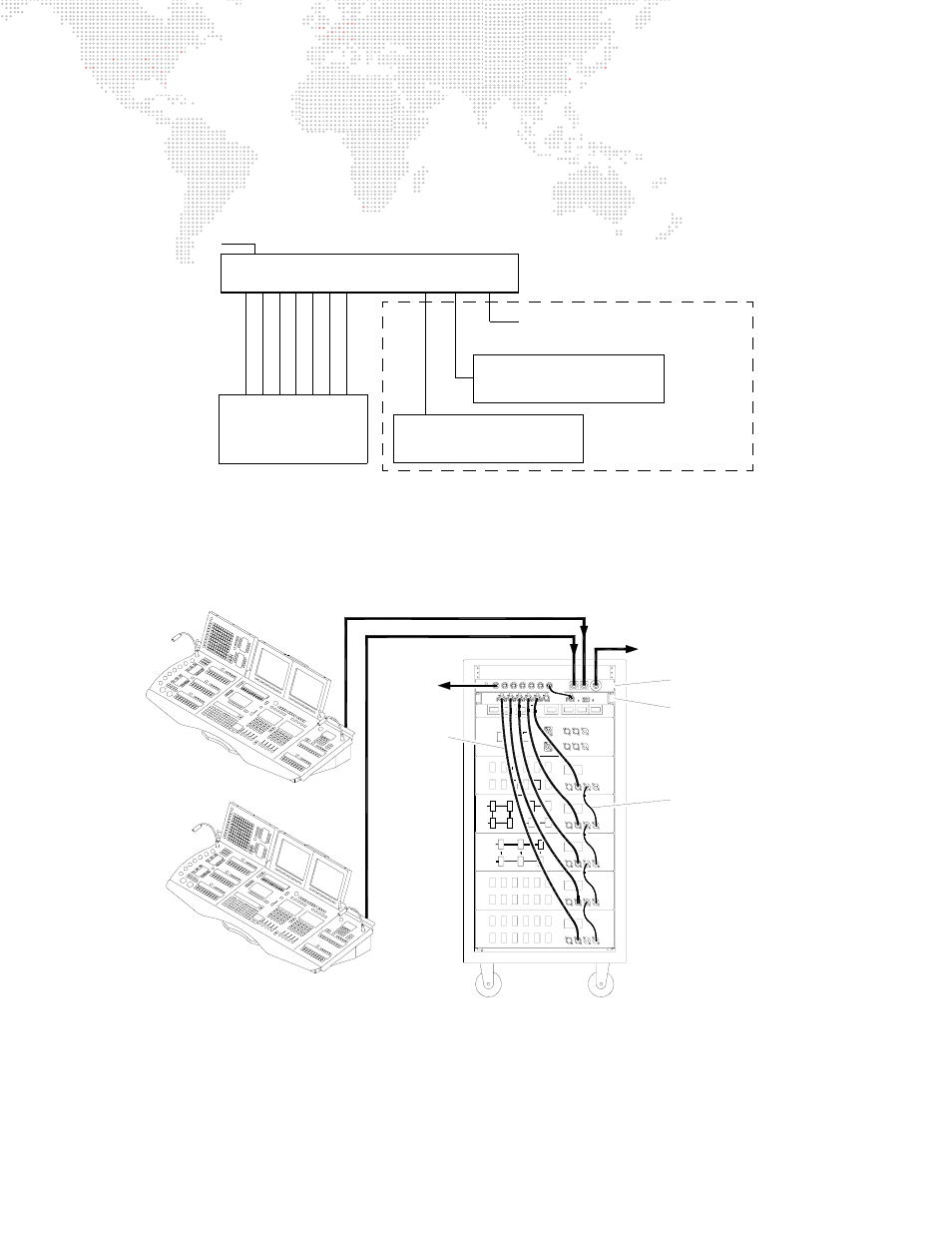
Figure 8: Device Connection Diagram
The following example system diagrams illustrate an Ethernet Switch being used with a Series 400 Power and Data
Distribution Rack.
Figure 9: Sample System Connection Diagram 1
AC Input
Fiber Optic Out to Additional Switches
10
/10
0
Base-
T
10
/10
0
Base-
T
10
/10
0
Base-
T
10
/10
0
Base-
T
10
/10
0
Base-
T
10
/10
0
Base-
T
10
/10
0
Base-
T
Fib
e
r O
p
tic
Fib
e
r O
p
tic
Virtuoso Nodes
or
Any Ethernet Device
(up to 7)
SERIES 400 ETHERNET SWITCH
Input from
a Virtuoso/V676 Console
or another switch
Input from
a Virtuoso/V676 Console
or another switch
10-Port Model Only
* Fiber optic connections available only with the 10-Port Ethernet Switch model.
SERIES 400 RACK
B
B
B
A
VIRTUOSO NODE
PRG S-400 10-PORT
ETHERNET SWITCH
A
B
A
A
SWITCHES
TO OTHER
FIBER OPTIC CABLE
FIBER OPTIC CABLE
DEVICES
TO OTHER
VIRTOUSO CONSOLE A
VIRTOUSO CONSOLE B
CAT5e CABLES
DMX UNIVERSE
CABLES