Power supply – Potter PFC-7500 Series User Manual
Page 23
19
22.4
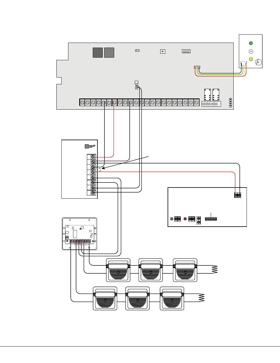
SNM Class B Style W Multiple Notification Appliance Circuits
1 AUX PWR
2 GND
3 Alarm In
4 Bell PWR In
5 Bell Out +
6 Bell Out -
7 Bell Trouble
8 Bell Trouble
Normal/Silence Switch
Potter Model SNM
45mA @ 12 VDC
The SNM Notification
Appliance Circuit
Module in alarm draws
up to 31mA through
its Terminal 3 Alarm
Input and 45mA from
its Terminal 1 Aux
Power Input.
Panel Reset
AC
1
2
3
4
7
8
10 11 12 13
14 15 16
AC
B+
B-
9
RED
YEL
GRN BLK
Z1B-
Z2 -
Z2+
1
2
3
4
J12
Z1A- Z1B +
Z1A +
PFC-7500 Series Commercial Fire Command
Processor Panel
MAIN
BACKUP
J11
N/C COM N/O N/C COM N/
O
Telephone Connections
J10 Trouble Annunciator Header
5
6
BELL
SM K
O
U
TP
U
T
1
O
U
TP
U
T
2
SILENCE/RESET
PUSH FOR ONE SECOND
S ilence/Reset
B utton
S ilence/Reset
Header
17 18
Z3 -
Z3+
19 20
Z4 -
Z4+
21 22
Z5 -
Z5+
Bell
Monitor
r
J13
J14
Power Supply
J6
+ DC -
AC
Trouble
Batt
Trouble
J4
J3
J2
Green
LED
AC
AC
+ BAT -
Red
LED
DC
12 VDC @ 5 Amps
Battery
Start
TAM Module
Auxiliary Power Supply must be regulated, power
limited, and listed for Fire Protective Signaling
Service. Power Supplies must have battery backup.
Note: If an auxiliary power supply is not used,
terminals 3 and 4 can be jumpered together to
supply Bell Power from the panel.
The Auxiliary Power Supply and Notification
Circuit Module trouble contact zone must be
programmed as a Supervisory Type zone.
MINUS 2
MINUS 1
+OUT 1
+IN 1
+IN 2
-AUD
+AUD
+OUT 2
10K EOLR
DSM-12/24 Module
10K EOLR
Listed, Polarized Notification Appliances
Sync module required
when using multiple
notification appliances
When using a separate power supply, the
maximum current is 3 Amps.
See the Notification Appliance section for a list of appliances.
The Bell Output
programming for Fire
type zones must be set
to Steady.
The maximum voltage drop
between the panel Bell Output and
the Model 308 is .5 VDC when a
separate power supply is not used.
Regulated
12 VDC