Perfect Aire 1PAMSH22-15 Installation Manual User Manual
Page 2
Install the outdoor unit on a rigid base to prevent increasing noise level and vibration.
Determine the air outlet direction where the discharged air is not blocked.
In the case that the installation place is exposed to strong wind such as a seaside, make
sure the fan operates properly by putting the unit lengthwise along the wall or using a dust
or shield plate.
In windy area, install the unit to prevent the admission of wind. If need suspending
installation, the installation bracket should accord with technique requirement in the
installation bracket diagram. The installation wall should be solid brick, concrete or the same
intensity construction, or actions to reinforce, damping supporting should be taken.
The connection between bracket and wall, bracket and the air conditioner should be firm,
stable and reliable.
Be sure there is no obstacle which block radiating air.
Strong
wind
Strong
wind
Barrier
Incorrect
Correct
Seal
Drain joint
Base pan hole
of outdoor unit
(A)
(B)
The drain joint is slightly different according to the
different outdoor unit.
For the drain joint with the seal (Fig.A), first fit the seal onto
the drain joint, then insert the drain joint into the base pan
hole of outdoor unit, rotate 90 to securely assemble them.
To install drain joint as shown in Fig.B, insert the drain
joint into the base pan hole of outdoor unit until it remains
fixed with a clicking sound. Connecting the drain joint with
an extension drain hose (locally purchased), in case of the
water draining off the outdoor unit during the heating mode.
2
DRAIN JOINT INSTALLATION
OUTDOOR INSTALLATION PRECAUTION
3
REFRIGERANT PIPE CONNECTION
Bar
Copper pipe
Clamp handle
Handle
Bar
"A
"
Indoor unit tubing
Flare nut
Pipings
Outer
diam.
Tightening
torque(N.cm)
Additional tightening
torque(N.cm)
1/4
1/2
5/8
3/8
1500
(153kgf.cm)
1600
(163kgf.cm)
3500
(357kgf.cm)
4500
(459kgf.cm)
3600
(367kgf.cm)
4700
(479kgf.cm)
2500
(255kgf.cm)
2600
(265kgf.cm)
AIR PURGING AND TEST OPERATION
4
5
Cover
Screw
Terminal block of outdoor unit
9k,12k,18k (Liquid side: 1/4 )
R410A: 0.212oz/ft
22k (Liquid side: 3/8 ):
R410A: 0.423oz/ft
Connective pipe length
Less than 16.41ft
More than 16.41ft
Air purging method
Use vacuum pump
Additional amount of refrigerant to be charged
Open the valve stem until it hits against
the stopper. Do not try to open it further.
Securely tighten the valve stem cap with
a spanner or the like.
Valve stem cap tightening torque. See
Tightening Torque Table.
Flare nut
Stopper
Cap
Valve body
Valve stem
Use vacuum pump
For the R410A refrigerant model, make sure the refrigerant added into air conditioner is liquid
form in any case.
When relocating the unit to another place, use vacuum pump to perform evacuation.
The indoor unit and tubing between the indoor and outdoor unit must be leak tested and evacuated
to remove any noncondensables and moisture from the system.
Check that each tube (both liquid and gas side tubes) between the indoor and outdoor units have
been properly connected and all wiring for the test run has been completed.
Pipe length and refrigerant amount:
Outdoor
unit
Indoor
unit
Refrigerant
Packed valve
Flare nut
Gas side
Liquid side
A
C
D
B
1. Completely tighten the flare nuts, A, B, C, D, Connect
the manifold valve charge hose to a charge port of the
packed valve on the gas pipe side.
2. Connect the charge hose connection to the vacuum
pump.
3. Fully open the handle Lo of the manifold valve.
4. Operate the vacuum pump to evacuate. After starting
evacuation, slightly loosen the flare nut of the packed
valve on the gas pipe side and check that the air is
entering. (Operation noise of the vacuum pump changes
and a compound meter indicates 0 instead of minus).
5. After the evacuation is complete, fully close the handle
Lo of the manifold valve and stop the operation of the
vacuum pump.
Make evacuation for 15 minutes and more and check
5
that the compound meter indicates -76cmHg(-1.0x10 Pa).
O
6. Turn the stem of the packed valve B about 45 counter-
clockwise for 6~7 seconds after the gas coming out, then
tighten the flare nut again. Make sure the pressure display
in the pressure indicator is a little higher than the atmosphere
pressure.
7. Remove the charge hose from the Low pressure charge hose.
8. Fully open the packed valve stems B and A.
9. Securely tighten the cap of the packed valve.
Manifold valve
Compound meter
-76cmHg
Handle Lo
Handle Hi
Charge hose
Charge hose
Vacuum pump
Pressure gauge
Packed valve
Perform test operation after completing gas leak check at the flare nut connections and electrical
safety check.
Check that all tubing and wiring have been properly connected.
Check that the gas and liquid side service valves are fully open.
1. Connect the power, press the ON/OFF button on the remote control to turn the unit on.
2. Use the MODE button to select COOL, HEAT, AUTO and FAN to check if all the functions work
well.
O
3. When the ambient temperature is too low (lower than 62.6 F), the unit cannot be controlled by the
remote control to run at cooling mode, manual operation can be taken. Manual operation is
used only when the remote control is disabled or maintenance necessary.
Hold the panel sides and lift the panel up to an angle until it remains fixed with a clicking sound.
Press the Manual control button to select the AUTO or COOL, the unit will operate under Forced
AUTO or COOL mode (see User Manual for details).
4. The test operation should last about 30 minutes.
1. Air purging
2. When using the Vacuum Pump
4. Test running
3. Safety and leakage check
A: Lo packed valve B: Hi packed valve
C and D are ends of indoor unit connection.
CAUTION
1. Soapy water method:
Apply a soapy water or a liquid neutral detergent on the indoor
unit connections and outdoor unit connections by a soft brush
to check for leakage of the connecting points of the piping. If
bubbles come out, it indicates that the pipes have leakage.
2. Leak detector
Use the leak detector to check for leakage.
O
U
T
D
O
O
R
U
N
I
T
CONNECT THE CABLE TO THE OUTDOOR UNIT
CAUTION
1
Indoor unit
check point
D
B
C
A
Outdoor unit
check point
Cover
NOTE:
Manual control
button
AUTO/COOL
Oblique Roughness Burr
O
90
Connective pipe installation
CAUTION
Outdoor unit installation
I
N
D
O
O
R
U
N
I
T
To indoor unit
To indoor unit
To power supply
To power supply
L1 L2 S L1 L 2
L1 L2 S L1 L 2
(1)
(2)
Outer diam.
(Inch)
A (inch)
Max.
Min.
0.052
0.03
3/8
0.063
0.04
0.087
0.079
1/4
1/2
5/8
0.04
0.071
Tightening connection
1. Remove the eclectrical control board cover from the outdoor unit by loosening the screw.
2. Attach the electrical whip from the outdoor disconnect to the proper connections shown in
the wiring diagram.
3. Connect the cable from the indoor unit as identified with their respective matching numbers
on the terminal block of the indoor unit.
4. Secure the cables on the control board with the supplied clamp.
5. Do not allow any bare wires to touch any other wires or metal parts.
Connect the indoor unit first, then the
outdoor unit.
Be careful not to let the drain hose slack.
Heat insulation should be done to the
extension drain hose of indoor unit.
Be sure that the drain hose is located at
the lowest side of the bundle. Locating at
the upper side can cause drain pan to
overflow inside the unit.
Never intercross nor intertwist the power
wire with any other wiring.
Both the liquid and suction refrigerant lines
must be insulated.
1. Install the outdoor unit on concrete or plastic pad or
mount to a wall with the proper brackets and secure
per local and national codes. Make sure the unit is level.
2. Make sure the unit has 12 inches of clearance on the
back, 12 inches on the left side (as you face the unit),
24 inches on the right side and 6-1/2 feet in the front.
3. Install the outdoor unit in a location where the noise
and vibration level with not be an issue.
4. Select a place so the warm air and noise from the
outdoor unit does not disturb neighbors.
Flaring
1. Cut the copper tube with a pipe cutter. Clean and
remove any burrs from the end of the pipe.
2. Remove the flare nuts attached to the indoor and
outdoor unit. Slide the nuts on the copper tube.
3. Insert copper tube into a flaring block and use the
table to determine how much tube should be above
the block before flaring the tube. You can also figure
the thickness of a nickel to use as a standard.
Align the tube to the proper connections on
the indoor and outdoor units.
Sufficiently tighten the flare nut with fingers,
and then tighten it with a crescent wrench and
torque wrench as shown.
Excessive torque can break nut depending
on installation conditions.
Indoor unit installation
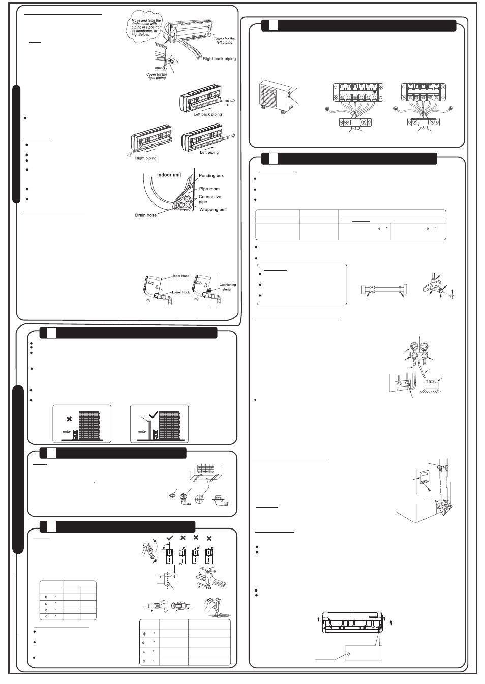
1. Pass the piping through the hole in the wall.
2. Hook the indoor unit onto the upper portion of installation plate (engage the indoor unit with the upper
edge of the installation plate). Ensure the hooks are properly seated on the installation plate by moving
it in left and right.
3. Piping connections can be easily made by lifting the indoor unit with a cushioning material between the
indoor unit and the wall. Remove after finished piping.
4. Press the lower left and right side of the unit against the installation plate until hooks engage with the
slots.
1. For the left-hand and right-hand piping,
remove the pipe cover from the side panel.
2. For the right back and left back piping, install
the piping as shown.
NOTE: One side drainage structure is standard.
Both sides drainage structure is optional and can
only be customized from factory. For both sides drainage
structure, it can be choosen for right, left or both sides
drainage connection. If choosing both sides drainage
connection, another proper drain hose is needed as
there is only one drain hose offered by factory. If
choosing one side drainage connection, make sure the
drain hole on the other side is well plugged.
For 9k/12k models, if choosing right side drainage connection,
please choose right-hand or right-back piping. The connection of the
drain hose is supposed to be done by qualified installer in case of
water leakage.
3. Bundle the tubing, connecting cable, and drain hose with tape
securely, evenly as shown in Figure on the right.
Because the condensed water from rear of the indoor unit is
gathered in the drain pan and is piped out of room do not put
anything else in the drain pan.