A) am loop antenna connection, B) fm wire antenna connection, Speakers connection – Philips FW555C37 User Manual
Page 11: Subwoofer out connection, 0 digital out connection, 0 connecting other, Equipment to your system, Ac power supply, Inserting batteries into the remote control
Attention! The text in this document has been recognized automatically. To view the original document, you can use the "Original mode".
(A)
AM Loop Antenna
Connection
Connect the supplied loop antenna to the
AM ANTENNA terminal. Place the AM loop
antenna far away from the system and
adjust its position for the best reception.
(
b
) FM Wire Antenna
Connection
Connect the supplied FM wire antenna to
the FM ANTENNA 300 Q terminal. Adjust
the position of the FM antenna for the best
reception.
Outdoor Antenna
For better FM stereo reception, connect an
outdoor FM antenna to tbe FM ANTENNA
300 Q terminal using a 300 dipole wire.
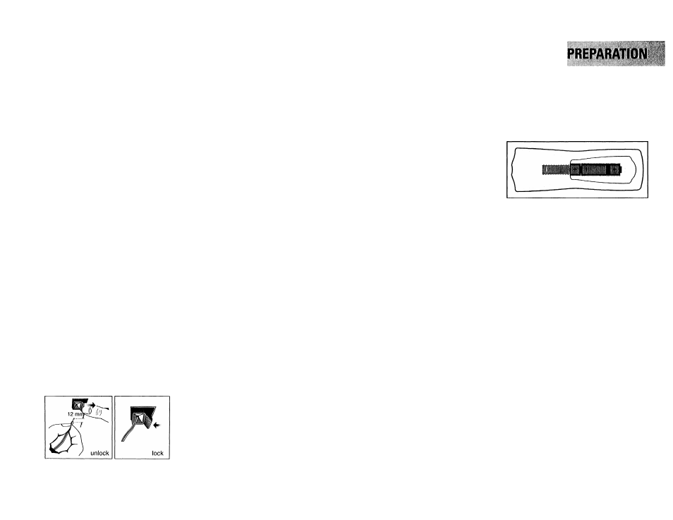
© Speakers Connection
• Connect the right speaker to Front
terminal R, with the red wire to + and
the black wire to —.
• Connect the left speaker to Front
terminal L, with the red wire to + and
the black wire to —.
• Clip the stripped portion of the speaker
wire as shown.
@
Subwoofer Out Connection
Connect the optional active subwoofer to
the SUBWOOFER OUT terminal. The
subwoofer reproduces just the low bass
effect (e.g. explosions, the rumble of
spaceships, etc.). Be sure to follow the
instructions supplied with the subwoofer.
(D
Line Out Connection
(wireless
ready)
You can connect the audio left and right
LINE OUT terminals to a optional CD
Recorder ANALOGUE IN terminals. This
allows you to record in an analogue format.
You can also install additional optional
front active speakers away from the
system (e.g. in another room) to reduce the
inconvenience of running long speaker
wires across rooms. You can place as many
remote speakers as you like provided they
operate at the same radio frequency.
Connect the wireless radio frequency
transmitter to the LINE OUT terminals.
Place the active speakers at your preferred
location. Be sure to follow the instructions
supplied with the active speakers.
Note:
- Availability of a wireless transmitter and
its peripherals is subjected to the
approval of local authorities. Please
check with your local safety or
approving authority.
0 Digital Out Connection
You can record the digital sound from the
CD, through this output, on any audio
equipment with digital input (e.g. CD
Recorder, Digital Audio Tape (DAT) deck.
Digital to Analog Converter and Digital
Signal Processor).
Connect one end of the cinch cable (not
supplied) to the DIGITAL OUT socket and
the other end to the audio equipment with
digital input.When connecting the cinch
cable, make sure it is fully inserted.
0 Connecting other
equipment to your system
You can connect the audio left and right
OUT terminals of a TV, VCR, Laser Disc
player, DVD player or CD-Recorder to the
AUX IN terminals at the rear of the system.
® AC Power Supply
After all other connections have been
made, connect the AC power cord to the
system and to the wall outlet.
Inserting batteries into the
Remote Control
• Insert the batteries (Type ROB or AA)
into the remote control as shown in the
battery compartment.
• To avoid damage from possible battery
leakage, remove dead batteries or
batteries that will not be used for a long
time. For replacement, use type ROB or
AA batteries.
11