Connecting with the ec-2, Led display – O.S. Engines 160FX-FI User Manual
Page 8
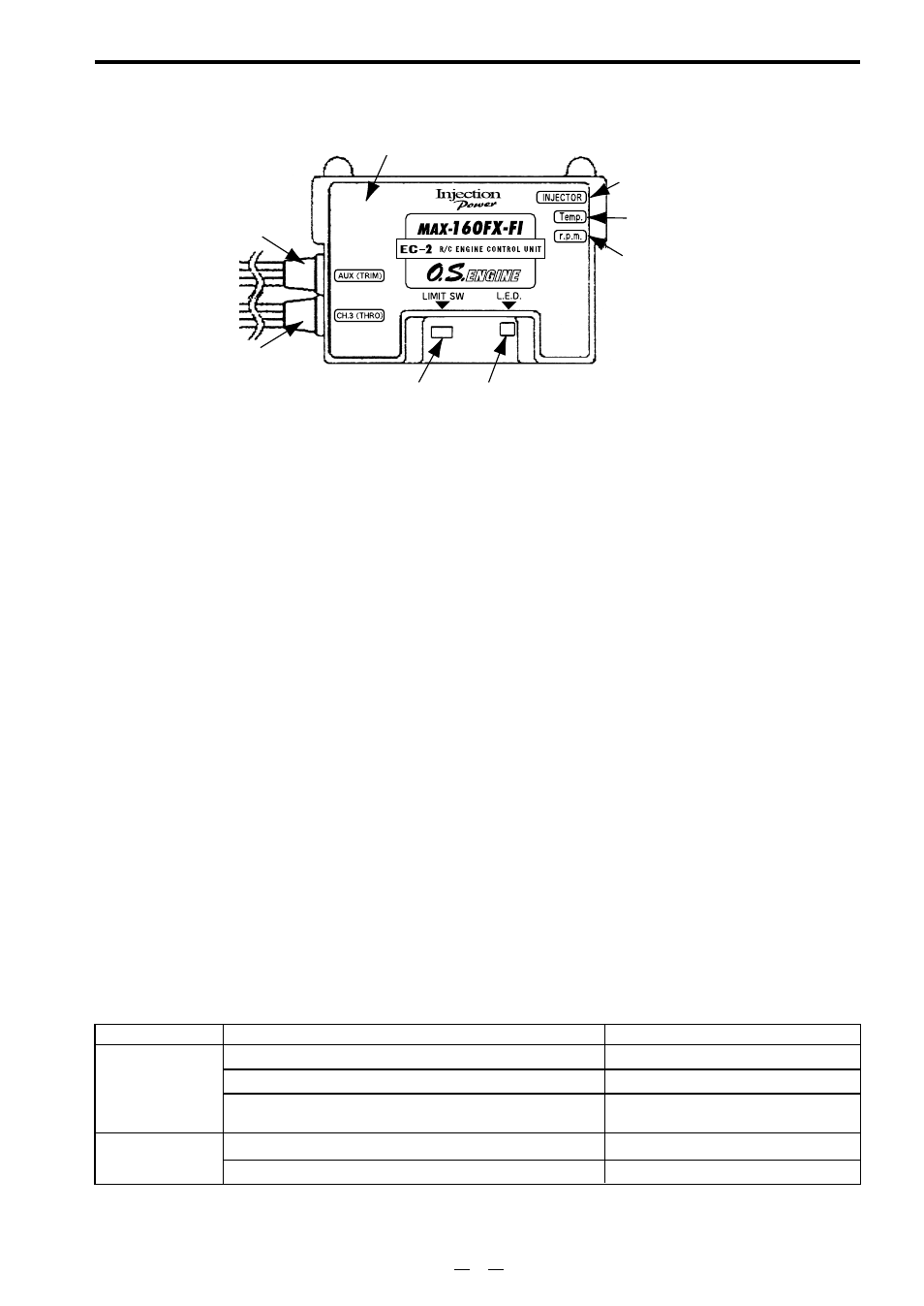
CONNECTING WITH THE EC-2
Connect the receiver and servo-related components (rudder section) in the same manner as in the past.
(5) RPM sensor input terminal
(r.p.m.)
(1) Injection time input terminal
(CH3:THRO)
Two extension cords (sold separately) of a length corresponding to the airframe are required for
connecting (1) and (2).
(1) Injection Time Input Terminal
receiver (throttle: CH3), connect the wiring connector from the throttle servo to one of the double-
opening connectors on the opposite side, and connect the other double-opening connector to
CH3:THRO of EC-2. (Use the separately sold extension cord if the wiring cords are too short.)
(2) Injection Trim Input Terminal
(Use the separately sold extension cord if the wiring cords are too short.)
(3) Injector Output Terminal
Connect the injector connector to the injector output terminal. Protect the lead wire with a heat-
resistant tube,etc. if it makes contact with the engine mount.
(4) Temperature Sensor Input Terminal
Connect the temperature sensor connector to the temperature sensor input terminal.
(5) Rotation Sensor Input Terminal Connect the rotation sensor connector to the rpm input terminal.
(2) Injection trim input terminal
(AUX:TRIM)
(3) Injector output terminal
(INJECTOR)
(4) Temperature sensor input terminal
(Temp)
(8) Integrated Buzzer
(6) Limit Setting Switch(LIMIT) (7) L.E.D.
(6) Limit Setting Switch(LIMIT) Push with driver supplied when setting limit.
(7) L.E.D.(Display of green and red)
It flashes or changes color when setting and cheking limit, and adjusting injection trim. It flashes with the color of
the injection trim when the engine is running.
LED Display
When the engine
is not running
When the engine
is running
Transmitter Operation
LED Status
Red lights
Green lights
Flashes
(color depends or the dial position)
Red flashes
Green flashes
Turn the dial right to reduce injection volume.
Turn the dial right to reduce injection volume.
Turn the dial left to increde injection volume.
Turn the dial left to increde injection volume.
Limit position
*Turning direction of dial shows the standard setting direction.
*Dial position shows plus (green - rich) or minus (red - lean) from the zero position (basis injection volume.)
7