4 hydraulic plumbing for rg2 (jic fittings) – NORAC UC4.5-BC-RG6 User Manual
Page 29
26
8.4 Hydraulic Plumbing for RG2 (JIC Fittings)
From this point on in the installation the booms will be inoperative until the
hydraulics are fully installed.
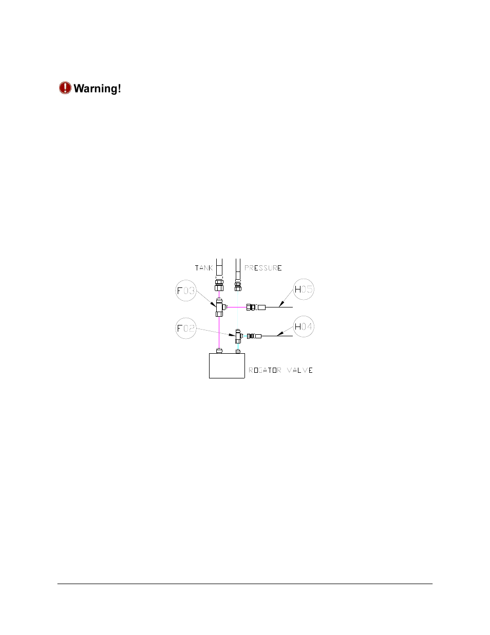
1. After the NORAC valve is mounted, the hydraulic hoses and fittings can be plumbed. The
plumbing for the hydraulic circuit is shown schematically in Figure 3.
2. Disconnect the tank line at the sprayer’s valve block and insert the 8FJXR 8MJT tee (F03).
3. Connect hose H05 to the tee and route to the NORAC valve block.
4. Disconnect the pressure line at the sprayer’s valve block and insert the 6FJXR 6MJT tee
(F02).
5. Connect hose H04 to the tee and route to the NORAC valve block.
Figure 22: Sprayer Pressure and Tank Plumbing
6. Connect hose H04 to the pressure port and hose H05 to the tank port on the NORAC
valve block.
7. Connect H07 and H08 to the “B” ports on the NORAC valve block. Route the hoses to
the tilt cylinders. H08 is longer than H07 since the NORAC valve block is normally located
on the right side of the sprayer.
8. Disconnect the existing hoses from the tilt cylinders and connect H07 and H08 to the
cylinders using the 12FJ 6MJ fittings (F05).
9. Install a 12MJP fitting (F06) and the 6MBP plug (F08) onto the ends of the existing raise lines
that were just removed.
10. The existing lower lines do not need to be modified. Leave these lines connected to the
sprayer valve block