NORAC UC4.5-BC-RG6 User Manual
Page 24
21
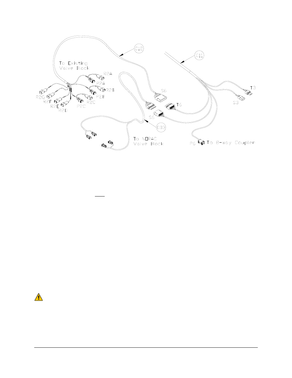
Figure 17: Cable Configurations: C03, C12 and C11
6. Run cable C11 to the rear of the sprayer, in the vicinity of the valve block.
7. Connect the 6-pin shroud on C12 to T6 on C11.
8. Route the free end of C12 to the sprayer’s valve block.
9. Insert 3 sets of the Deutsch connector tees (which are labeled as “MAIN UP”, “MAIN UP”
and “MAIN DOWN” on the branch wires) between the matching sprayer main control
valve connections: HOIST UP (MAIN UP), HOIST DN (MAIN DOWN) (Figure 18). (Both
“MAIN UP” tees have the same functionality and can be matched to the HOIST UP
connection(s)).
10. Unplug the existing connectors on the sprayer left and right boom control valve
connections. There are 4 connectors to unplug: LH FOLD UP (LEFT UP), LH FOLD DN
(LEFT DOWN), RH FOLD UP (RIGHT UP) and RH FOLD DN (RIGHT DOWN).
11. Plug in the 2-pin Deutsch connectors of C12 to the matching connectors of sprayer’s
cable(s). For each connector, the function (e.g. “LEFT UP”, etc.) is labeled on the branch
wire of C12.
Alternate cabling is available from NORAC if the connectors on C12 do not
match the valve block. Refer to Table 1 on page 10.