NORAC UC4.5-BC-NT3 User Manual
Page 19
16
Ensure the UC4.5 Control Panel’s power is OFF for the remaining installation.
(Bottom of switch pressed IN).
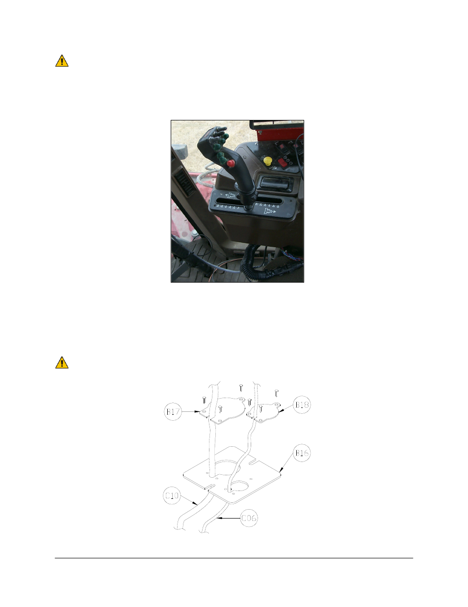
6. Locate the 16-pin AMP connector attached to the sprayer’s joystick and connect the 16-pin
AMP tee connectors of C10 between this connection.
Figure 15: Joystick Connection
7. There is an access hole located in the front right corner of the cab floor that can be seen
when the floor mat is lifted. Access plates (B16, B17 and B18) which maintain the cab seal
are provided in the UC4.5 kit. Rout C06 and C10 through the small hole and large hole in
the access plate (Figure 16).
Leave the cover plates (B17 and B18) unscrewed at this point.
Figure 16: Access plates configurations
See also other documents in the category NORAC Gardening equipment:
- UC4.5-BC-AP3 (35 pages)
- UC4.5-BC-AS1 (22 pages)
- UC4.5-BC-CS1 (34 pages)
- UC4.5-BC-CS2 (35 pages)
- UC4.5-BC-CS3 (36 pages)
- UC4.5-BC-CS5 (42 pages)
- UC4.5-BC-EU1 (42 pages)
- UC4.5-BC-FC1 (29 pages)
- UC4.5-BC-FC2 (32 pages)
- UC4.5-BC-FT1 (32 pages)
- UC4.5-BC-FT3 (33 pages)
- UC4.5-BC-GN1 (38 pages)
- UC4.5-BC-GN2 Part 1 (20 pages)
- UC4.5-BC-GN2 Part 2 (11 pages)
- UC4.5-BC-GN6 (22 pages)
- UC4.5-BC-HD1 (32 pages)
- UC4.5-BC-HD3 Part 1 (36 pages)
- UC4.5-BC-HD3 Part 2 (7 pages)
- UC4.5-BC-HD4 Part 1 (45 pages)
- UC4.5-BC-HD4 Part 2 (7 pages)
- UC4.5-BC-HD5 Part 1 (31 pages)
- UC4.5-BC-HD5 Part 2 (10 pages)
- UC4.5-BC-HD7 (39 pages)
- UC4.5-BC-HD9 (24 pages)
- UC4.5-BC-JD6 (37 pages)
- UC4.5-BC-JD7 (42 pages)
- UC4.5-BC-JD8 (35 pages)
- UC4.5-BC-JD8A (46 pages)
- UC4.5-BC-JD11 (33 pages)
- UC4.5-BC-MC1 (31 pages)
- UC4.5-BC-MC2 (31 pages)
- UC4.5-BC-MS1 (32 pages)
- UC4.5-BC-NT4 (35 pages)
- UC4.5-BC-PS1 (38 pages)
- UC4.5-BC-RA1 (42 pages)
- UC4.5-BC-RA2 (27 pages)
- UC4.5-BC-RG2 (38 pages)
- UC4.5-BC-RG4 (36 pages)
- UC4.5-BC-RG5 (35 pages)
- UC4.5-BC-SC2 (33 pages)
- UC4.5-BC-SC4 (28 pages)
- UC4.5-BC-SM2 (30 pages)
- UC4.5-BC-SS1 (34 pages)
- UC4.5-BC-TA1 (36 pages)