5 hydraulic plumbing – single acting – NORAC UC4.5-BC-HD7 User Manual
Page 29
26
8.5 Hydraulic Plumbing – Single Acting
From this point on in the installation the booms will be inoperative until the
hydraulics are fully installed.
1. After the NORAC valves are mounted, the hydraulic hoses and fittings can be plumbed
following the schematic in Figure 4.
2. Install the 90 degree fittings on hoses H02 onto the “B” ports on the NORAC valve block.
3. Route the free ends of the hoses to each of the wing tilt cylinders.
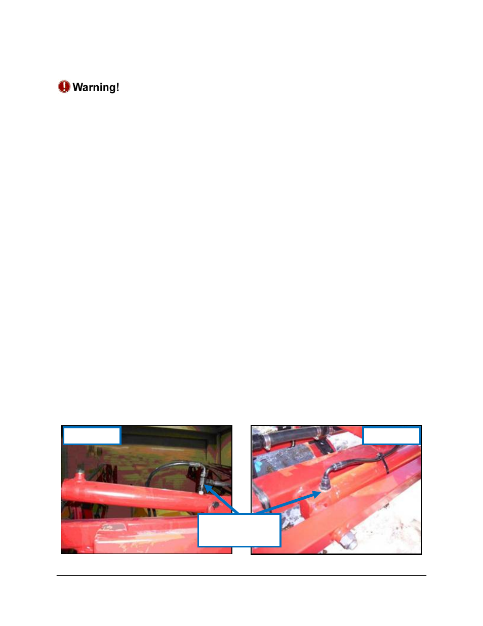
4. Remove the Hardi hoses from the “raise” line (“B” line) of the cylinder and remove the
restricted straight BSPP fittings. (Figure 25) Install the 4FBSPPX 6MJ fittings (F04) onto
hoses H02. Install NORAC and Hardi hoses onto the 4MBSPPT 4FBSPPRX tee (F05).
5. At the Hardi main valve block, remove the hydraulic hoses that run from the “raise” line of
the tilt cylinders to the valve block (Figure 24). Remove the fittings from between the
hoses and valve block.
6. Install the restrictor that was removed from the wing tilt cylinder between the hoses and
the valve block.
7. Install the fittings that were removed from the valve block between the cylinders and tee
fittings (F05).
8. Remove the pressure and tank hoses from the Hardi valve block and install the 4MBSPPT
4FBSPPRX tee (F05) between the valve block and hoses. Install the 4FBSPPX 6MJ fittings
(F04) onto hoses H01.
9. Connect hoses H01 to each of the tee fittings and route to the NORAC valve block. Install
the corresponding hose to the pressure and tank port on the NORAC valve block.
Figure 25: Restrictor to be Replaced on the Tilt Cylinders
Eagle Boom
Force Boom
Replace this
Restrictor