NORAC UC4.5-BC-HD7 User Manual
Page 23
20
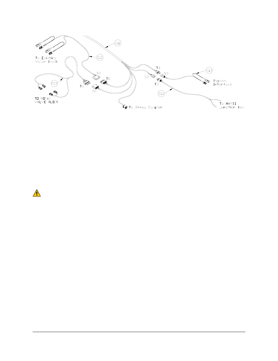
Figure 19: Cable Configurations: C03, C11, C12, C13 and C16
7. Connect the 6-pin shroud (S6) on the valve interface cable (C12) to T6 on C11. Route C12
to the Hardi main lift valve block located on the bottom of the sprayer near the axle.
8. Insert the 2 sets of tees between the matching Hardi main lift valve connections in
accordance to the labels on the wires.
9. Connect the 3-pin tower (T3) on the roll pigtail cable (C16) to S3 on C11.
10. Connect the wires labeled “LEFT” and “RIGHT” on C16 to the Hardi left and right tilt
cartridge valve, respectively.
C16 may have labels “CW” and “CCW” on it in place of “LEFT” and
“RIGHT”, respectively.
11. Connect the 3-pin shroud on C13 to T3 on C11. Insert the tee on C13 between the
connectors on the bypass valve.
12. Connect the 6-pin tower on C03 to the 6-pin shroud on C11. Connect the 2-pin
connectors on C03 to the NORAC valve block, as shown in Figure 20.
13. The connectors on the valve cable (C03) are marked RIGHT UP, LEFT UP, RIGHT
DOWN and LEFT DOWN. Cables labeled with UP go on the same side as the
hydraulic hoses.