NORAC UC4.5-BC-GN6 User Manual
Page 19
16
6. Route C11 to the vicinity of the valve block at the rear of the sprayer.
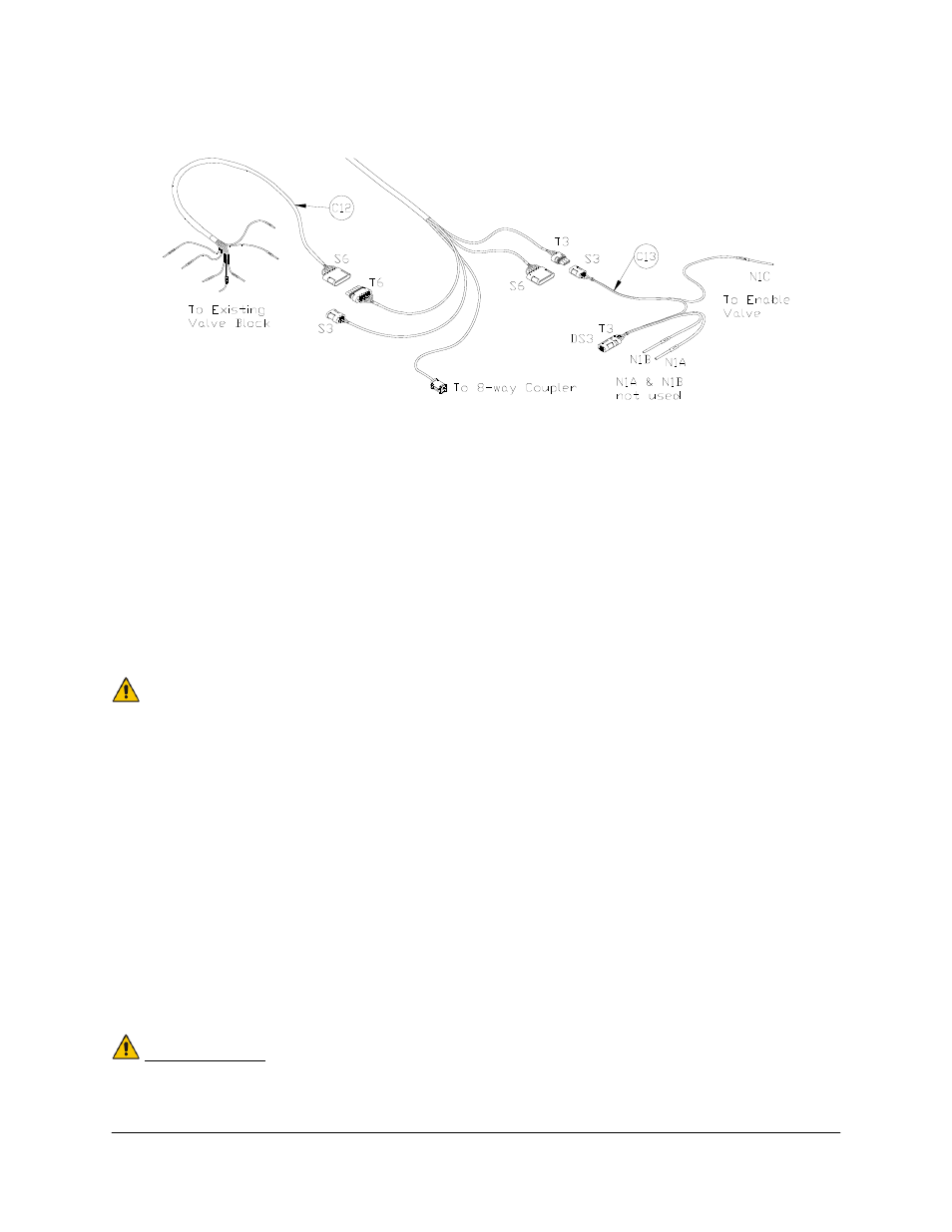
Figure 18: Cable Connections
7. Connect the 6-pin shroud (S6) on the interface cable (C12) to the mating 6-pin tower (T6)
on C11.
8. Route the free end of C12 to the existing valve block.
9. Connect the wires of C12 to the matching valve connections.
10. Connect the 3-pin shroud (S3) on C13 to the mating 3-pin tower (T3) on C11.
11. Connect N1C on C13 to the bypass valve.
See UC4.5-BC-CABLE-GUIDE cable ordering guide for more information.
12. Fasten the 8-way coupler to the boom with cable ties. Connect P6 on C11 to the 8-way
coupler.
13. Connect both roll sensors to the 8-way coupler.
14. Connect two cables (C05) to the 8-way coupler and route along the booms to the wing
sensors. Follow existing cables and hoses to be sure the cable will not be pinched or
stretched.
15. At the sensor brackets, attach a 2-way coupler with terminator (E20) to the sprayer boom.
The 2-way coupler with terminator is the white two way coupler. Plug the sensor and the
CANbus cable into the 2-way coupler.
16. Insert the 6-pin plugs (P03) into the unused connectors on the 8-way coupler (E11).
IMPORTANT:
Provide enough slack in all cables to account for all boom movement and
FOLDING boom movement.