NORAC UC4.5-BC-CS5 User Manual
Page 24
21
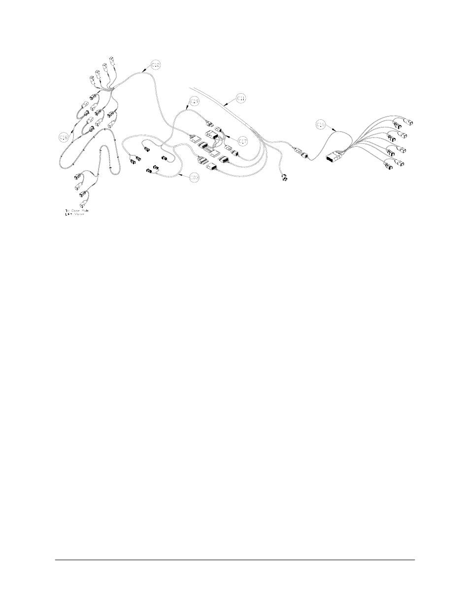
Figure 22: Cable Configurations: C03, C11, C12, C16, C17, C18 and C19
6. Run cable C11 to the rear of the sprayer, in the vicinity of the valve block.
7. Connect the unplugged 6-pin shroud on cable C17 to the 6-pin tower on cable C11.
8. Connect the 3-pin shroud labeled “Connect to C11” on cable C17 to the 3-pin tower on
cable C11.
9. Connect the 3-pin tower (T3) on roll sense interface cable (C16) to S3 on C11.
10. Route the free end of cable C16 to the existing left and right boom control valve block.
11. Insert the 2-pin tees (R2A-P2A - R2D-P2D) of C16 between the matching valve connections
(Left Up, Left Down, Right Up, Right Down).
12. Insert the 2-pin plugs (P01) into connectors R2D, R2E, R2F and R2G on cable C12.
13. Connect the 6-pin shroud on C12 to T6 on C17.
14. Connect the 2-pin tees (labeled “MAIN UP” and “MAIN DOWN” on the branch wires) of
C12 to the matching tees of the main extension interface cable (C18). There is an extra
“MAIN UP” tee (R2A and P2A) on C12. This extra tee is not used for this installation.
15. Route the free end of C18 to the existing main control valve block.
16. Insert the 2-pin tees (R2C-P2C and R2D-P2D) of C18 between the matching main control
valve connections.
17. Connect the valve interface cable (C03) to connector S6 on the valve extension cable
(C11).