NORAC UC4.5-BC-AP3 User Manual
Page 22
19
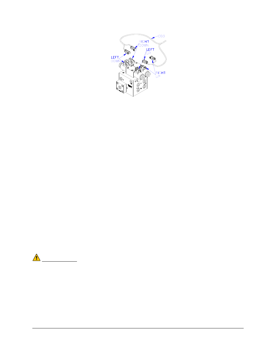
Figure 21: Valve Cable Connections
14. Fasten the 8-way coupler (E11) to the boom with cable ties.
15. Connect P6 on C11 to the 8-way coupler (E11).
16. Connect the chassis roll sensor (reference frame) the 8-way coupler using cable C06 and a
2-way coupler (E12).
17. Connect the boom frame roll sensor and intermediate frame roll sensor to the 8-way
coupler.
18. Connect the main lift sensor to the 8-way coupler using cable C07 and a 2-way coupler
(E12). Cable C07 and item E12 may not be needed if the 8-way coupler is mounted close
enough to the main lift sensor.
19. Connect two cables (C05) to the 8-way coupler and route along the booms to the wing
sensors. Follow existing cables and hoses to be sure the cable will not be pinched or
stretched.
20. At the sensor brackets, attach a 2-way coupler with terminator (E20) to the sprayer boom.
The 2-way coupler with terminator is the white two way coupler. Plug the sensor and the
CANbus cable into the 2-way coupler.
21. Insert the 6-pin plug (P03) into the unused connector on the 8-way coupler (E11).
IMPORTANT:
Provide enough slack in all cables to account for the movement of the main
section, parallel lift, and FOLDING boom movement.