MUTEC MC-4 User Manual
Page 21
\\\\\\\\\\\\\\\\\\
A N H A N G
A N H A N G
A N H A N G
> > > > > > > > > > > > > > > > > > > > > > > > > > > > > > > > > > > > > > > > > > > > > > > > > > > > > > > > > > > > > > > > > > > >
> > > > > > > > > > > > > > > > > > > > > > > > > > > > > > > > > > > > > > > > > > > > > > > > > > > > > > > > > > > > > > > > > > > >
88
Manual SDs-01 D 3.2.2003 17:45 Uhr Seite 16
X-SRC
12
BI-DIR
UNI-DIR
ADAT
1
SMUX4
1
SRC
REFERENCE
IN 3
IN 2
IN 1
IN 4
SMUX4
SMUX2
ADAT
AES3
88.2
48.0
44.1
32.0
192.0
96.0
176.4
MODE
SMUX2
1
AES3
2
AUDIO
IN
S/P-DIF
S/P-DIF
AES11
WCLK
21
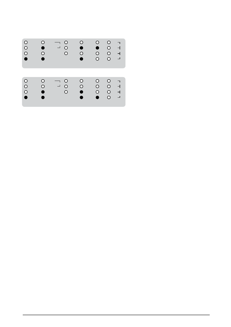
Further Setting Examples
Bidirectional format and sampling rate conversion between SMUX2 and an 8-channel AES3 signal.
The AES3 signals are all referenced to the second AES3 input signal.
X-SRC
12
BI-DIR
UNI-DIR
ADAT
1
SMUX4
1
SRC
REFERENCE
IN 3
IN 2
IN 1
IN 4
SMUX4
SMUX2
ADAT
AES3
88.2
48.0
44.1
32.0
192.0
96.0
176.4
MODE
SMUX2
1
AES3
2
AUDIO
IN
S/P-DIF
S/P-DIF
AES11
WCLK
Bidirectional format and sampling rate conversion between SMUX4 and an 8-channel AES3 signal.
The AES3 signals are all referenced to the fourth AES3 input signal.
STATUS
This area displays different system conditions of your MC-4. There is no
access for changing settings.
»LOCK
1
« and »LOCK
2
«
Doing unidirectional format conversions or bidirectional format conversions
with SRC, the »LOCK
1
« LED lights when the internal PLL circuit has detected
the incoming digital audio signal or clock reference signal as valid. During
bidirectional format conversions or the different X-SRC modes, the »LOCK
1
«
and »LOCK
2
« LEDs light both, when the incoming digital audio signals are
valid. As it is only possible to do bidirectional conversions between ADAT
TM
or SMUX2/4 and AES3, the first LED »LOCK
1
« is assigned to the optical input
and the second LED »LOCK
2
« is assigned to the AES3 inputs.
If the digital audio or reference clock signal is unstable, the »LOCK
1
« and/
or »LOCK
2
« LEDs do not light, the whole audio conversion process will be
stopped and the digital audio outputs do not transmit any signals.
If the internal oscillator is selected as reference clock, the »LOCK
1
« LED will
light correspondingly.
»SMUX2 + SMUX4 ADAT OUT«
These two LEDs light correspondingly, if an SMUX2/4 signal with a sampling
rate between 50.0kHz and 100.0kHz (SMUX2), or with a sampling rate
between 100.0kHz and 200.0kHz (SMUX4) is output. These LEDs are not
reporting any state of the optical inputs!
CLOCK
IN
»1« + »2«
This area displays the incoming reference clock rates for the different states
of operation of the MC-4.
When working with unidirectional format conversion only, the sampling
rate of the digital audio signal, which is selected as reference, will be
displayed under »1«. Doing unidirectional format and sampling rate
conversion, the clock rate of the selected reference clock signal will be
displayed »1« as well.
When working with bidirectional conversion modes, the two LED lines are
pre-assigned for ADAT
TM
or SMUX2/4 with »1« and for AES3 signals with »2«.
If the internal oscillator supplies the reference clock for the SRCs, the clock
rate which is selected in the »REFERENCE« menu will be displayed under »1«.